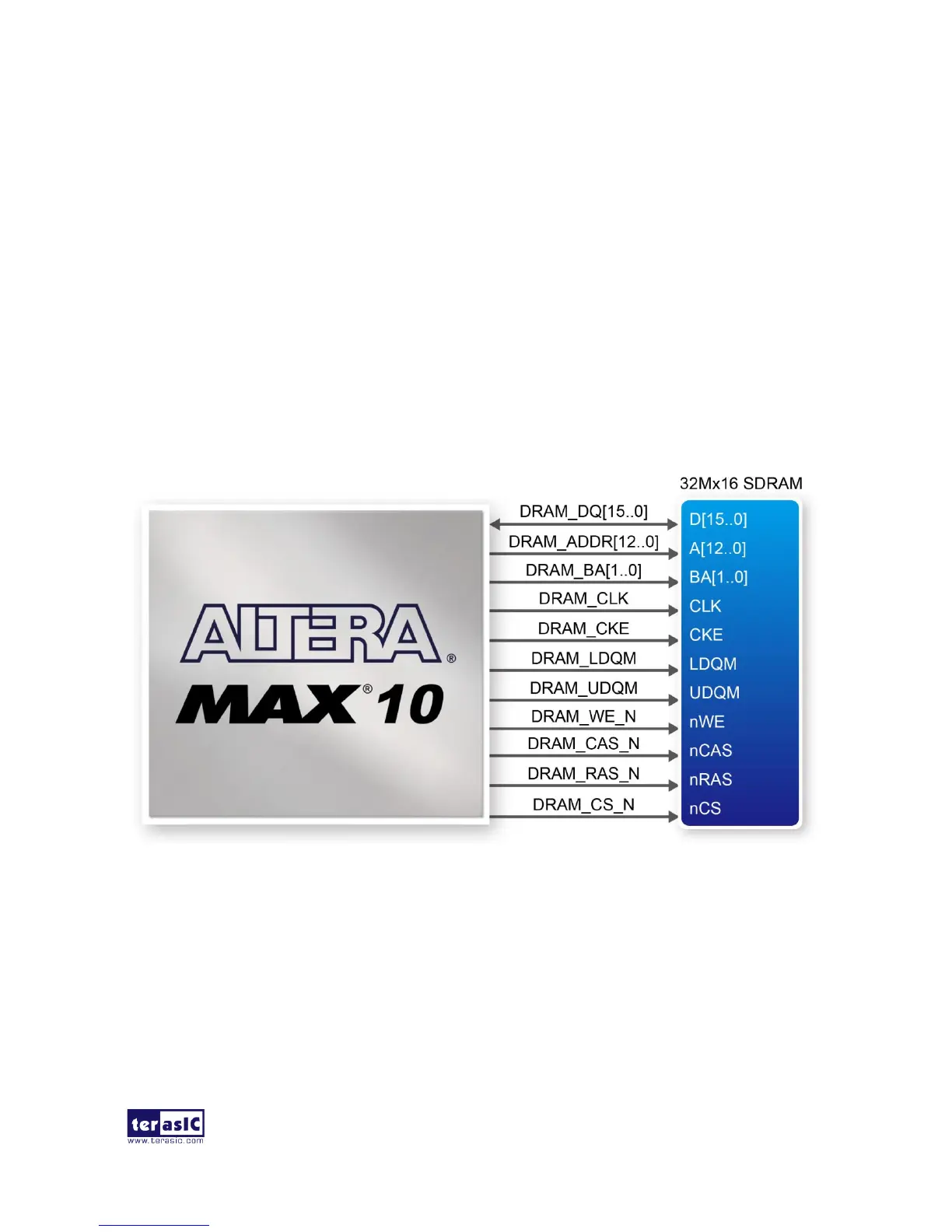
The board features 64MB of SDRAM with a single 64MB (32Mx16) SDRAM chip. The chip
consists of 16-bit data line, control line, and address line connected to the FPGA. This chip uses the
3.3V LVCMOS signaling standard. Connections between the FPGA and SDRAM are shown in
Figure 3-23, and the pin assignment is listed in Table 3-12. Detailed information on using the
SDRAM is available on the manufacturer’s website, or under the \Datasheets\SDRAM folder on the
DE10-Lite System CD.
Figure 3-23 Connections between the SDRAM and MAX 10 FPGA
 Loading...