◼ User-Defined LEDs
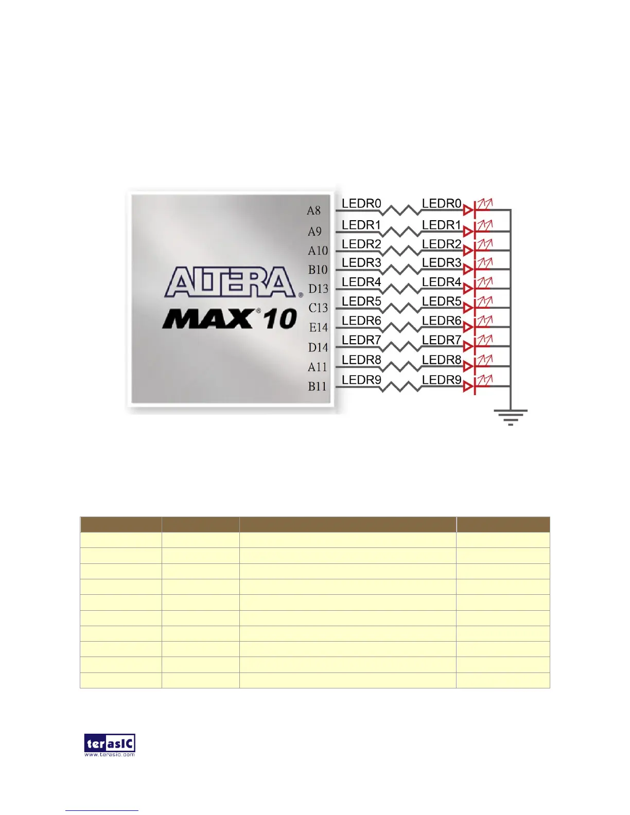
There are also ten user-controllable LEDs connected to FPGA on the board. Each LED is driven
directly and individually by a pin on the MAX 10 FPGA; driving its associated pin to a high logic
level turns the LED on, and driving the pin low turns it off. Figure 3-16 shows the connections
between LEDs and MAX 10 FPGA. Table 3-5 list the pin assignment of user LEDs.
Figure 3-16 Connections between the LEDs and MAX 10 FPGA
Table 3-5 Pin Assignment of LEDs
 Loading...