IBUC Operation Manual
Terrasat Communications, Inc.
Rev. A
2-3
Certain considerations must be taken when selecting the IFL since appropriate shielding
and signal levels are required for normal system operation. The IBUC is designed to
operate with a –30 dBm TX L-band input signal to achieve rated power at maximum
gain. The IBUC provides a user accessible variable attenuator that allows the gain of
the unit to be reduced by up to 16dB in 0.1dB steps. The attenuator can be used to
prevent overdrive to IBUC in configurations with a short cable run (IFL) and thereby
preserving Modem dynamic range. In addition the IBUC and LNB must have a 10MHz
input signal, at +3 to -12 dBm for the IBUC, and 0 to –10 dBm for the LNB. The
maximum voltage drop for a 24VDC BUC is 4 volts and for a 48VDC BUC is 11 volts.
PSUI (opt.)
48 VDC
Indoor
Equipment
Outdoor Equipment
Satellite Modem
Hand Held Terminal
IBUC
FSK
100-240VAC
TCP/IP, RS232, OR RS485
RX L-band
10 MHz, 24VDC
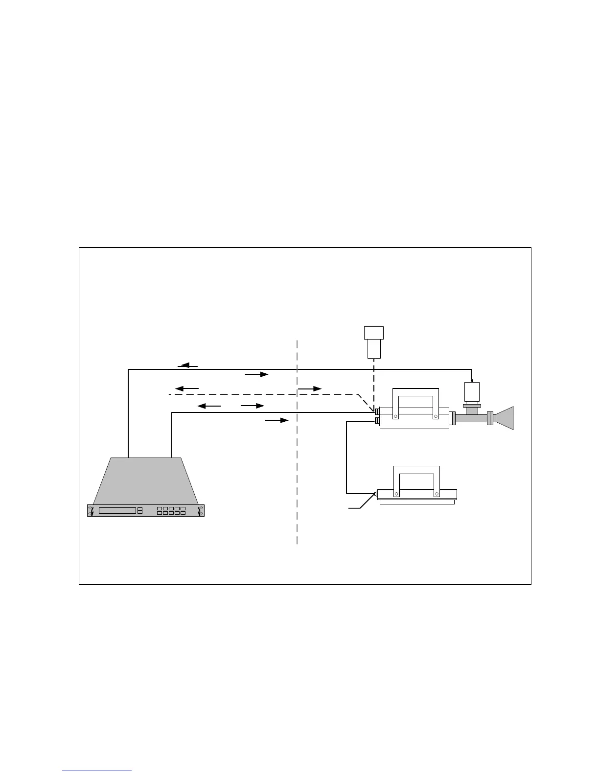
Low Power Configuration
5/10W C-band & 4/8/12W Ku-band
3
TX L-band / 10 MHz / DC
LNB
Note: 12W IBUC has a cooling fan
Figure 2-1 Low Power System Configuration