IBUC Operation Manual
Terrasat Communications Inc.
Rev. A
4-8
DC Power J3: Prime power is supplied to the IBUC through a 6-pin circular female
connector.
Table 4.3: IBUC Power Connector J3, Pin Assignments
IBUC J3
PIN FUNCTION
A VDC -
B VDC -
C VDC -
D VDC +
E VDC +
F VDC +
Note:
The IBUC is factory-configured for Positive Supply (+48VDC, standard) or Negative
Supply (-48VDC, optional). J3 is internally connected, as follows:
Positive Supply: VDC- is connected to Common.
Negative Supply: VDC+ is connected to Common.
RF OUT: The RF out connection is waveguide (WR-75) for Ku-band units and either
waveguide (WR-137) or N-type connector for C-band units.
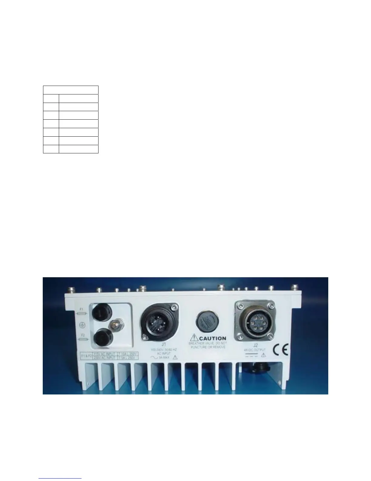
PSUI
Figure 4-2 PSUI Front Panel