IBUC Operation Manual
Terrasat Communications, Inc.
Rev. A
7-6
Switch Control
The M&C also controls and monitors both waveguide and relay switches. The
connection to the waveguide switch is through J7.
Emergency switches
The Rx 1+1 Interface Module also offer two switches (access through an access panel
on the Rx 1+1 module) that allows the operator to switch from system A to B when
something goes wrong with the M&C card. Switch SW1 changes the operation mode
from normal (controlled by the M&C) to emergency (manually controlled by the
operator). Switch SW2 allows the operator to change from system A to B. To access the
switches, just unscrew the small cover from the front panel. When in emergency mode
the LED labeled normal / emergency will turn red (green for normal operation).
LED Indicators
Similar to the transmit interface, the receive module has also a bank of LED’s that
provide a visual indication of the power (green if it’s OK), Ethernet activity, status of both
systems (which one is online and if there is a major alarm present), as well as the
normal / emergency LED, as previously explained.
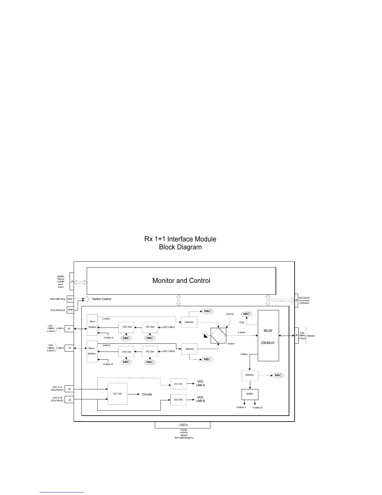
Figure 7-3 Rx 1+1 Interface Module Block Diagram