IBUC Operation Manual
Terrasat Communications Inc.
Rev. A
4-6
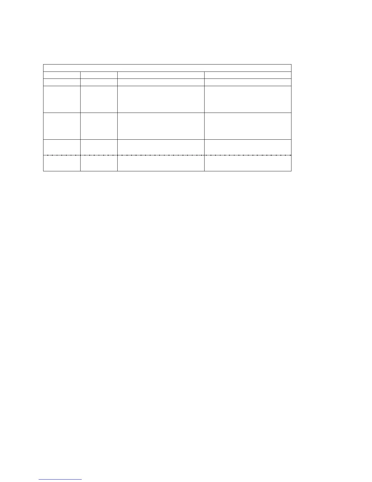
Table 4-1 IBUC Connector Schedule
IBUC CONNECTOR SCHEDULE
REF DESIG
FUNCTION
CONNECTOR CONNECTOR MATE
J1
TX IN
TYPE-N, RCPT (TYPE-F optional) TYPE-N PLUG (TYPE-F PLUG)
J2
M&C
INTERFACE
AMPHENOL CYLINDRICAL, BOX
MTG RCPT, 19S (MS3112E-14-19S)
AMPHENOL CYLINDRICAL,
STRAIGHT PLUG, 19P (MS3116F-
14-19P)
J3 DC POWER
CANNON MS CIRCULAR, BOX
MOUNTING RCPT (MS3102R14S-
6P)
CANNON MS CIRCULAR,
STRAIGHT PLUG (MS3106F14S-
6S)
RF OUT Ku-Band
WR75, COVER FLANGE WITH
GROOVE
WR-75 COVER FLANGE
RF OUT C-Band
CPR137, CPRG WAVEGUIDE or N-
Type (F)
CPR-137, CPRF, WAVEGUIDE or
N-TYPE (M)
A mating M&C connector for J2 or DC interface connector for J3 are available from
Terrasat. For IBUC’s with a rated power level of 12 watts and below the power for the
IBUC may be through the L-band IFL supplied from the satellite modem. The IBUC can
also be supplied directly through the external power connector (J3). Options are
available for 24VDC and 48VDC. Refer to the label on the unit to determine which
voltage is required.
For IBUC’s with a rated power of 16 watts or greater, an external power supply is
required. Terrasat offers a 400W outdoor PSUI (good for all power levels up to 40W C-
band or 25W Ku-band) and a 700W outdoor PSUI (good for all power levels up to 80W
C-band and 40W Ku-band). Power supplies have an auto-ranging AC front end that will
work with both 115VAC and 230VAC. The outdoor PSUI is shipped with a DC power
cable (10ft) and mating connectors for the AC mains power cable.
Transmit In J1: The TX IN connector is a Type N, female (Type F, female optional)
connector used to connect the IF at L-band from the modem to the IBUC. 50Ω cables
(75Ω for Type-F connectors) should be used to connect to J1. Certain considerations
must be taken when selecting the IFL since appropriate shielding and signal levels are
required for normal system operation. The IBUC is designed to operate at rated power
with a –30 dBm TX L-band input signal, with the variable attenuator set to minimum
attenuation. The variable attenuator is accessible through the M&C for system gain
adjustment. In addition the IBUC must have a 10MHz input signal between +3 to -12
dBm.
Once DC power and 10 MHz input signals are applied, the IBUC will function without
the necessity of an M&C interface.
For lower power units (12W and below) the cable should also be selected for its current
carrying capabilities. The low power IBUC can draw up to 4.5 amps at 37 VDC or 6