IBUC Operation Manual 3-4
Terrasat Communications, Inc.
Rev. A
Low Noise BlockConverter (LNB)
The LNB is available in Standard C-band, Palapa C-band, Insat C-band or one of three
Ku-band frequency bands. See Table 2-2 for actual frequencies. The C-band LNB
comes standard with a typical noise figure of 35
o
K and the Ku-band typical noise figure
is 60
o
K. The LNB houses the Low Noise Amplifier (LNA), the RX conversion circuitry,
and the L-band IF Interface (de-mux). The interface with the LNB is through a 50 or 75
Ω coaxial cable that carries the L-Band receive signal, 10 MHz reference oscillator
signal, and DC power.
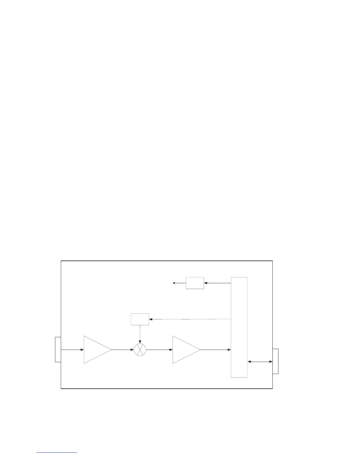
Refer to LNB block diagram.
The input to the LNB is a WR229 waveguide for C-band and WR75 waveguide for Ku-
band. The input to the LNB will typically be between –125 dBm and –80 dBm
depending on the system design (antenna size, satellite, number of carriers, etc.). The
LNB will amplify the RF input signal and downconvert it to an L-band signal. Like the
IBUC the DRO is phase locked to the 10MHz signal that has been multiplexed on to
the L-band output connector. The 10MHz input level must be between 0 and –10 dBm
and must meet the minimum phase noise requirements (see chapter 9). The DC
voltage is also multiplexed on to the L-band output connector and must be between 15
and 24VDC. Current consumption is typically less than 400mA.
LNB Block Diagram
RF
Input
LNA
L-band
10MHz
VDC
PL DRO
Power
Supply
IF - Amp
DE-MUX
All circuits
10 MHz
L-band
VDC
Figure 3-2 LNB Block Diagram