IBUC Operation Manual
Terrasat Communications, Inc.
Rev. A
7-12
Current and voltage surges in the AC power input can be reduced by installing surge
protectors and AC power line filters.
Note: AC transients and surges can cause data transmission errors.
To ensure uninterrupted service, some method of backup AC power is recommended.
An un-interruptible power supply (UPS) is preferred, along with a power stabilizer or an
isolation filter to ensure clean power.
System Cabling Requirements
Interfaces
TX System – IBUC’s A and B each connect to the interface box via a coax cable
connection (J1) carrying L-band, 10MHz reference and FSK M&C signals where
appropriate. A second connector on the IBUC (J2) connects to the interface box
providing M&C interface. IBUC waveguide outputs are connected to ports on the TX RF
switch using waveguide bends. DC Power (48VDC) is provided from separate power
supplies to each IBUC at J3.
The TX waveguide switch provides the uplink signal to the antenna feed via waveguide
(customer supplied) or coax cable as required. Power and switching control are carried
on an interface cable from the switch to the interface box.
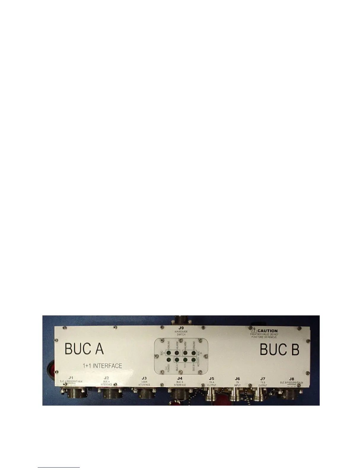
The interface box provides nine connectors for interfacing the IFL, IBUC’s RF switch
and M&C. Status LED’s are built in to the interface box providing visual system status.
Remote M&C for the 1+1 system is available via separate M&C cables using RS485 or
TCP/IP. Systems with FSK-capable modems also have M&C available at the modem
front panel. Local M&C is available with a hand held terminal connected at the interface
box.
Tx 1+1 Interface Module
Figure 7-4 Tx 1+1 Interface Module Top View