IBUC Operation Manual 3-3
Terrasat Communications, Inc.
Rev. A
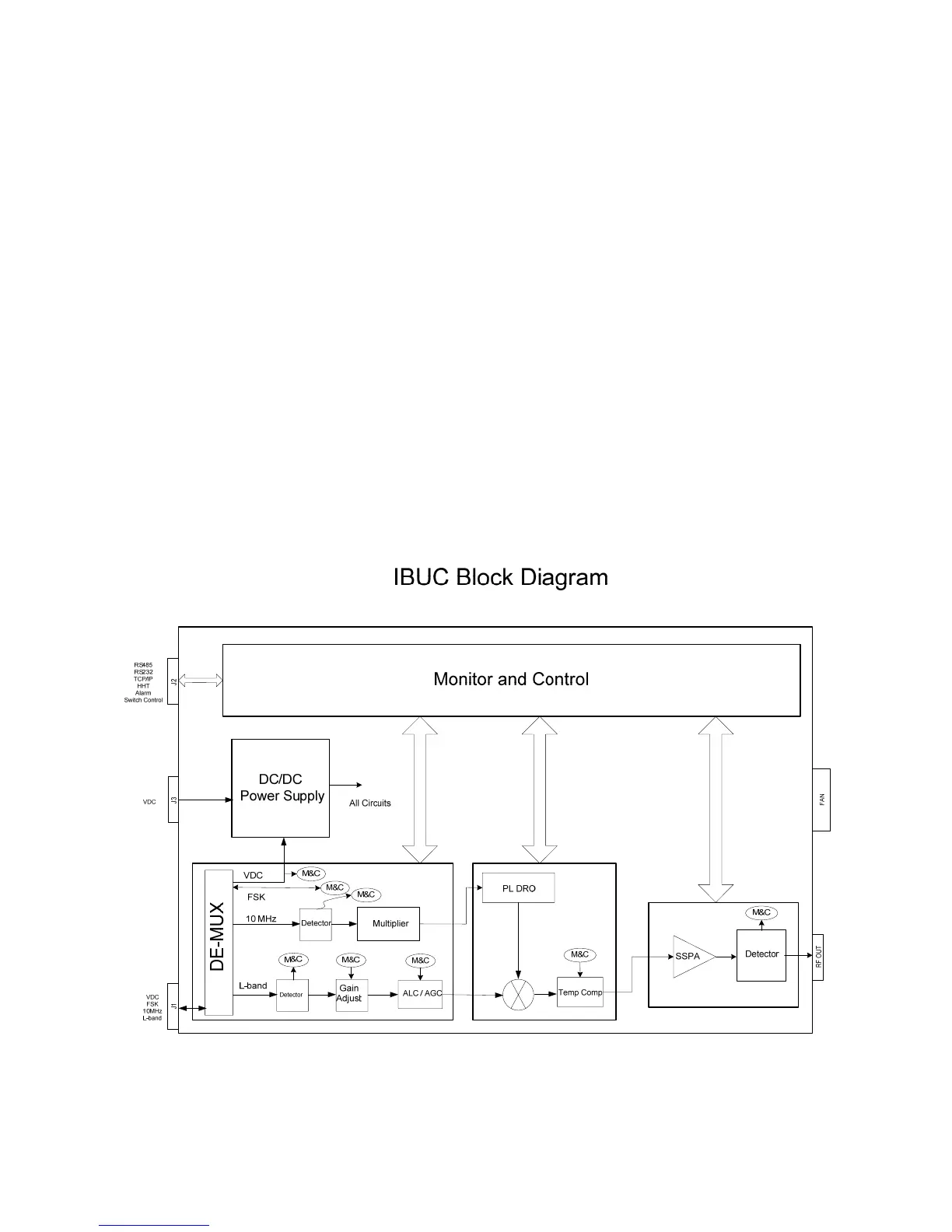
The L-band signal that is split off in the demultiplexer circuitry is first filtered and a
sample of it is detected for M&C purposes. The signal is then amplified, and goes
through two sections of Variable attenuators. The first one is used to provide a gain
adjustment of 16 dB in 0.1 dB steps to the user. The second one is used to provide
ALC (Automatic Level Control) or AGC (Automatic Gain Control).
After a few more sections of amplification and filtering the signal is routed to the mixer.
The mixer mixes the L-band signal with the DRO signal to “upconvert” to the
appropriate RF signal based on the frequency band of the IBUC. The RF signal is then
filtered, amplified and routed to the temperature compensation circuitry. The
temperature compensation circuitry has been calibrated over temperature so that the
IBUC gain does not vary more than 3dB at any frequency. The signal is then routed
through an isolator to the SSPA. The SSPA section then amplifies the signal which is
then routed to the output through an isolator for reverse power protection. The RF
output is detected for use by the M&C circuitry. The IBUC gain has been calibrated so
that at maximum gain, a –30 dBm input results in rated power output (P1dB) of the
IBUC. To operate at lower power levels simply reduce the input to the IBUC or simply
reduce the gain of IBUC using the variable attenuator (see Commands in Chapter 6).
The output of the C-band IBUC is a WR137 waveguide or N-type connector and WR75
waveguide for Ku-band.
Figure 3-1 IBUC Block Diagram