IBUC Operation Manual 3-6
Terrasat Communications, Inc.
Rev. A
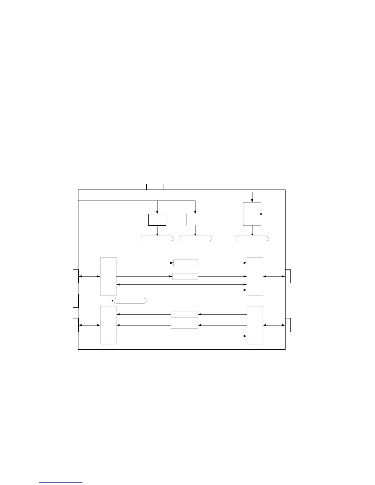
IN. On J5 (Rx OUT) there is 24V IN, 10MHz IN and L-Band OUT. There is also one
additional connector (J3) for external 10MHz input. On the front panel there is a small
hole that gives access to a trimpot (when the OCXO is installed) that allows the user to
adjust the frequency of the 10MHz reference. The internal 200W Power Supply can
power up to 12W IBUC’s. If configured with the 200W DC Supply, the chassis will be
equipped with a fan. The front panel is also provided with a green LED that allows the
user to verify if the unit is powered up.
IFU, Tx/Rx, Block Diagram
Fan
IBUC
Supply
LNB
Supply
IBUC Supply select
LNB Supply select
OCXO
VDC
Freq Adj
TX out to
IBUC
DC
FSK
10MHz
L-band
RX out to
Modem
L-band
M
u
x
/
D
e
m
u
x
M
u
x
/
D
e
m
u
x
M
u
x
/
D
e
m
u
x
M
u
x
/
D
e
m
u
x
10MHz select
10MHz select
IBUC Supply select
LNB Supply select
FSK
L-band
L-band
110 / 220 VAC
TX in from
Modem
RX in from
LNB
L-band
FSK
L-band
24 VDC
10 MHz
J1
J3
J4
External
10 MHz
J2
J5
10MHz select
10MHz select
Figure 3-3 IFU, Tx/Rx, Block Diagram
 Loading...
