www.ti.com
Testing the EVM Data Capture with LVDS Interface
13
SLOU489–August 2017
Submit Documentation Feedback
Copyright © 2017, Texas Instruments Incorporated
AFE5832 32-Channel Analog Front-End Evaluation Module (EVM Rev. A)
4. Ensure there is no SMA cable connected to J37 TX_Trig on the AFE5832EVM.
5. Turn switch 4 contained in S5 on the AFE EVM 'off' for LVDS only. The red LED, D8 should light up.
For more information on the Complex Programmable Logic Device (CPLD), refer to Section C.1.4.
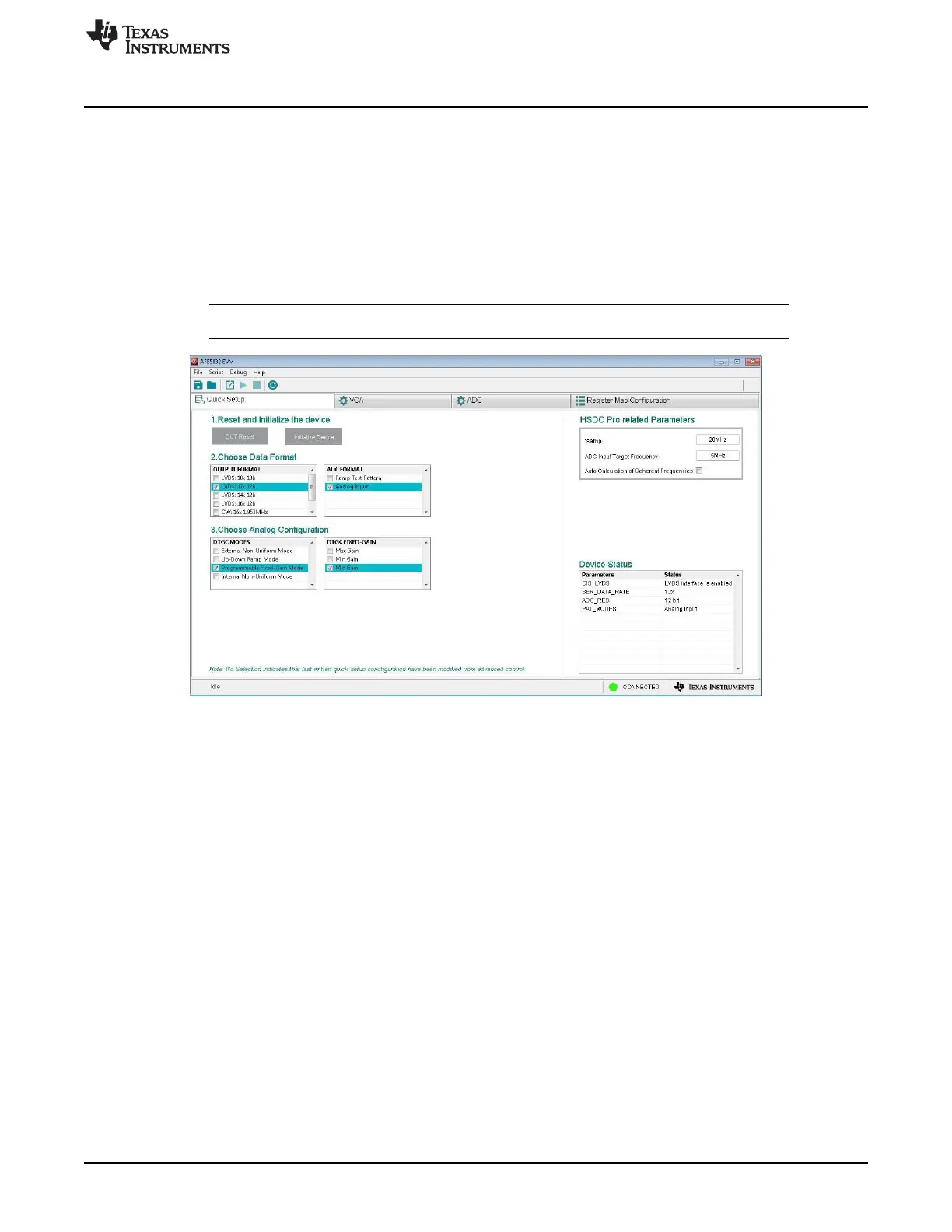
6. Choose the Data Formats and the Analog Configuration for each category as shown in Figure 12:
• OUTPUT FORMAT: Select ‘LVDS: 12x 12b’
• ADC FORMAT: Select ‘Analog Input’
• VCA GAIN: Select ‘Mid Gain’
• DTGC Modes: Select ‘Programmable Fixed-Gain Mode’
NOTE: Ensure the right CPLD switches are configured on S5 as detailed for each capture mode.
Figure 12. AFE5832 EVM GUI Data Format and Analog Configuration (LVDS)