AM3359, AM3358, AM3357, AM3356, AM3354, AM3352
www.ti.com
SPRS717H –OCTOBER 2011–REVISED MAY 2015
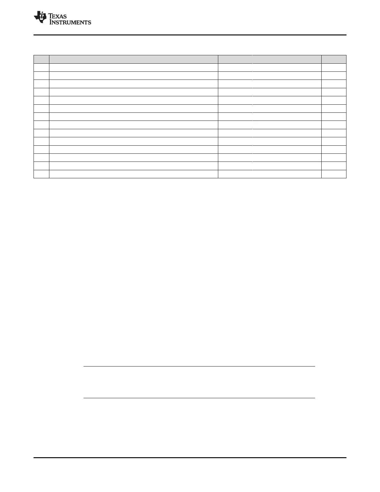
Table 7-66. CK and ADDR_CTRL Routing Specification
(1)(2)(3)
(continued)
NO. PARAMETER MIN TYP MAX UNIT
7 AS skew 25 mils
8 AS+ and AS– length 70 mils
9 AS+ and AS– skew 5 mils
10 AT length
(6)
500 mils
11 AT skew
(7)
100 mils
12 AT skew
(8)
5 mils
13 CK and ADDR_CTRL nominal trace length
(9)
CACLM-50 CACLM CACLM+50 mils
14 Center-to-center CK to other DDR3 trace spacing
(10)
4w
15 Center-to-center ADDR_CTRL to other DDR3 trace spacing
(10)(11)
4w
16 Center-to-center ADDR_CTRL to other ADDR_CTRL trace spacing
(10)
3w
17 CK center-to-center spacing
(12)
18 CK spacing to other net
(10)
4w
19 Rcp
(13)
Zo-1 Zo Zo+1 Ω
20 Rtt
(13)(14)
Zo-5 Zo Zo+5 Ω
(1) CK represents the clock net class, and ADDR_CTRL represents the address and control signal net class.
(2) The use of vias should be minimized.
(3) Additional bypass capacitors are required when using the VDDS_DDR plane as the reference plane to allow the return current to jump
between the VDDS_DDR plane and the ground plane when the net class switches layers at a via.
(4) Mirrored configuration (one DDR3 device on top of the board and one DDR3 device on the bottom).
(5) Non-mirrored configuration (all DDR3 memories on same side of PCB).
(6) While this length can be increased for convenience, its length should be minimized.
(7) ADDR_CTRL net class only (not CK net class). Minimizing this skew is recommended, but not required.
(8) CK net class only.
(9) CACLM is the longest Manhattan distance of the CK and ADDR_CTRL net classes + 300 mils. For definition, see Section 7.7.2.3.6.1
and Figure 7-66.
(10) Center-to-center spacing is allowed to fall to minimum (w) for up to 1250 mils of routed length.
(11) Signals from one DQ net class should be considered other DDR3 traces to another DQ net class.
(12) CK spacing set to ensure proper differential impedance. Differential impedance should be Z
o
x 2, where Z
o
is the single-ended
impedance defined in Table 7-60.
(13) Source termination (series resistor at driver) is specifically not allowed.
(14) Termination values should be uniform across the net class.
7.7.2.3.6.2 DQS[x] and DQ[x] Routing Specification
Skew within the DQS[x] and DQ[x] net classes directly reduces setup and hold margin and, thus, this skew
must be controlled. The only way to practically match lengths on a PCB is to lengthen the shorter traces
up to the length of the longest net in the net class and its associated clock. DQLMn is defined as DQ
Longest Manhattan distance n, where n is the byte number. For a 16-bit interface, there are two DQLMs,
DQLM0-DQLM1.
NOTE
It is not required, nor is it recommended, to match the lengths across all bytes. Length
matching is only required within each byte.
Given the DQS[x] and DQ[x] pin locations on the AM335x device and the DDR3 memories, the maximum
possible Manhattan distance can be determined given the placement. Figure 7-67 shows this distance for
a two-load case. It is from this distance that the specifications on the lengths of the transmission lines for
the data bus are determined. For DQS[x] and DQ[x] routing, these specifications are contained in Table 7-
67.
Copyright © 2011–2015, Texas Instruments Incorporated Peripheral Information and Timings 189
Submit Documentation Feedback
Product Folder Links: AM3359 AM3358 AM3357 AM3356 AM3354 AM3352
 Loading...