VSSOP28
1
2
3
4
5
6
7
8
9
10
11
12
13
14
28
27
26
25
24
23
22
21
20
19
18
17
16
15
PA20 / SWCLK
PA19 / SWDIO
VCORE
NRST
VDD
VSS
PA0
PA1
PA2 / ROSC
PA3 / LFXIN
PA4 / LFCLK_IN / LFXOUT
PA5 / HFXIN / FCC_IN
PA6 / HFCLK_IN / HFXOUT
PA9 / RTC_OUT / CLK_OUT
PA10 / CLK_OUT
PA11
PA16 / A1_1 / FCC_IN
PA15 / A1_0
PA14 / CLK_OUT / A0_12
PA18 / A1_3
PA17 / A1_2
PA25 / A0_2
PA24 / A0_3
PA22 / CLK_OUT / A0_7
PA21 / A1_7 / VREF-
PA27 / RTC_OUT / A0_0
PA26 / A0_1
PA23 / VREF+
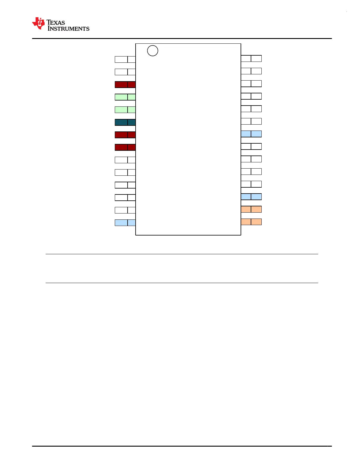
Figure 6-6. 28-Pin DGS28 (VSSOP) (Top View)
Note
For full pin configuration and functions for each package option, refer to Pin Attributes and Signal
Descriptions.
www.ti.com
MSPM0G3507, MSPM0G3506, MSPM0G3505
SLASEX6A – FEBRUARY 2023 – REVISED JUNE 2023
Copyright © 2023 Texas Instruments Incorporated
Submit Document Feedback
11
Product Folder Links: MSPM0G3507 MSPM0G3506 MSPM0G3505