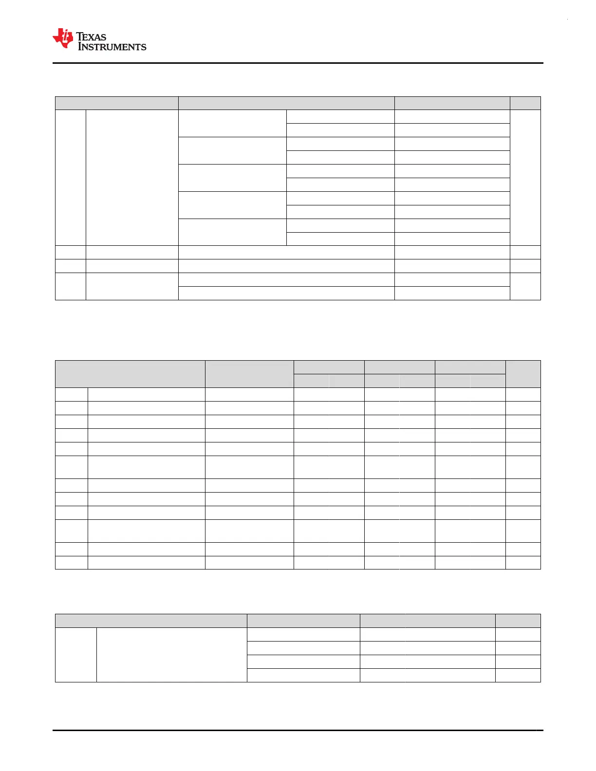
7.18.3 PGA Mode (continued)
over recommended ranges of supply voltage and operating free-air temperature (unless otherwise noted)
PARAMETER TEST CONDITIONS MIN TYP MAX UNIT
R
PGA
Programmable gain
stage resistance
GAIN = 0x1
R1 64
kΩ
R2 (feedback resistor) 64
GAIN = 0x2
R1 32
R2 (feedback resistor) 96
GAIN = 0x3
R1 16
R2 (feedback resistor) 112
GAIN = 0x4
R1 8
R2 (feedback resistor) 120
GAIN = 0x5
R1 4
R2 (feedback resistor) 124
G/dV Gain supply drift 0.02 1 %/V
G/dT Gain temperature drift 0.002 0.02 %/C
THD Total harmonic distortion
f
= 3kHz, R
L
= 1.5kOhm to VDD/2, GBW = 0x1, GAIN = 0x1 75
dB
f
= 188Hz, R
L
= 1.5kOhm to VDD/2, GBW = 0x1, GAIN = 0x5 55
7.19 I2C
7.19.1 I2C Characteristics
over operating free-air temperature range (unless otherwise noted)
PARAMETERS TEST CONDITIONS
Standard mode Fast mode Fast mode plus
UNIT
MIN MAX MIN MAX MIN MAX
f
I2C
I2C input clock frequency I2C in Power Domain0 2 32 8 32 20 32 MHz
f
SCL
SCL clock frequency 0.1 0.4 1 MHz
t
HD,STA
Hold time (repeated) START 4 0.6 0.26 us
t
LOW
LOW period of the SCL clock 4.7 1.3 0.5 us
t
HIGH
High period of the SCL clock 4 0.6 0.26 us
t
SU,STA
Setup time for a repeated
START
4.7 0.6 0.26 us
t
HD,DAT
Data hold time 0 0 0 ns
t
SU,DAT
Data setup time 250 100 50 ns
t
SU,STO
Setup time for STOP 4 0.6 0.26 us
t
BUF
bus free time between a STOP
and START condition
4.7 1.3 0.5 us
t
VD;DAT
data valid time 3.45 0.9 0.45 us
t
VD;ACK
data valid acknowledge time 3.45 0.9 0.45 us
7.19.2 I2C Filter
over operating free-air temperature range (unless otherwise noted)
PARAMETERS TEST CONDITIONS MIN TYP MAX UNIT
f
SP
Pulse duration of spikes suppressed by
input filter
AGFSELx = 0 5 5.5 32 ns
AGFSELx = 1 8 15 55 ns
AGFSELx = 2 18 38 115 ns
AGFSELx = 3 50 74 150 ns
www.ti.com
MSPM0G3507, MSPM0G3506, MSPM0G3505
SLASEX6A – FEBRUARY 2023 – REVISED JUNE 2023
Copyright © 2023 Texas Instruments Incorporated
Submit Document Feedback
47
Product Folder Links: MSPM0G3507 MSPM0G3506 MSPM0G3505