7 Specifications
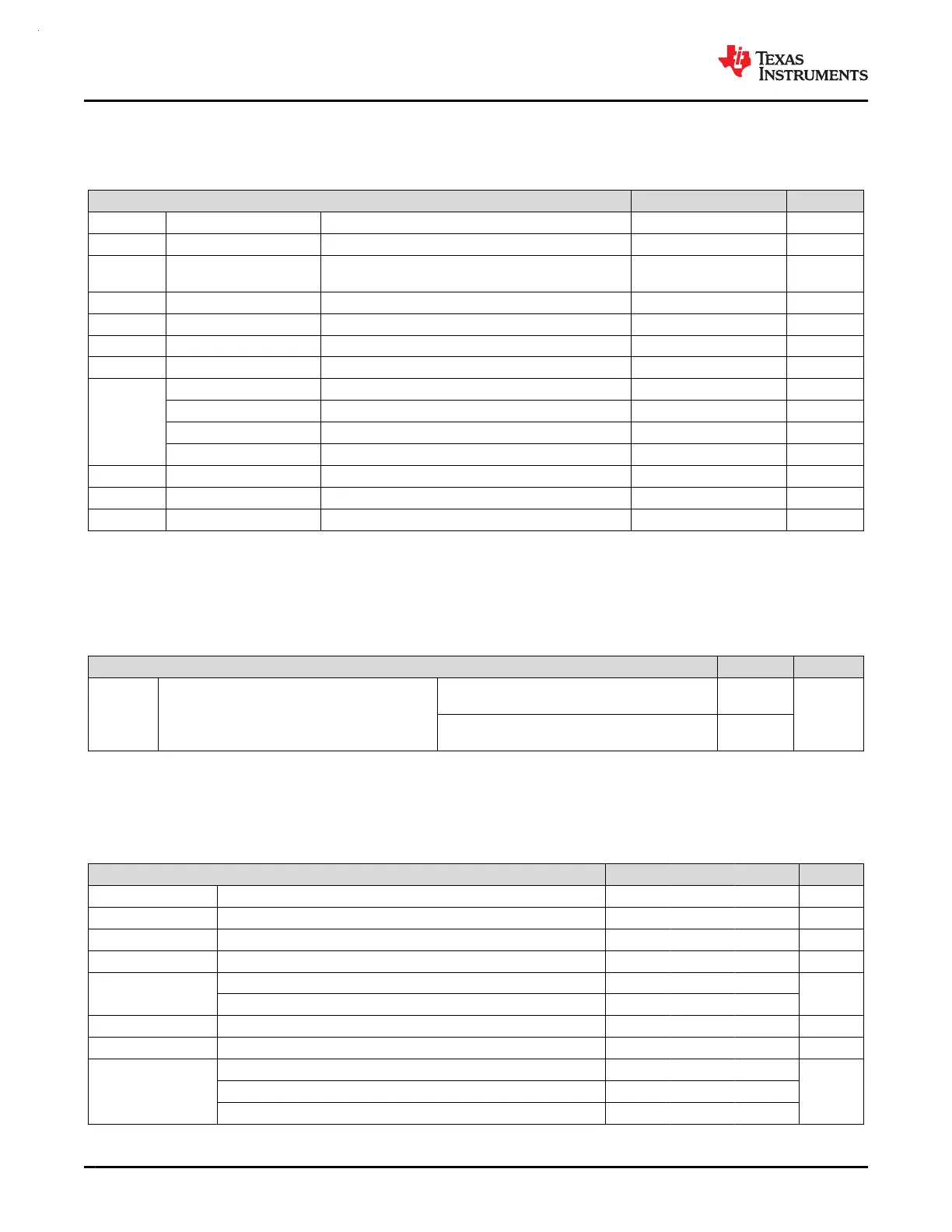
7.1 Absolute Maximum Ratings
over operating free-air temperature range (unless otherwise noted)
(1)
MIN MAX UNIT
VDD Supply voltage At VDD pin –0.3 4.1 V
V
I
Input voltage Applied to any 5-V tolerant open-drain pins –0.3 5.5 V
V
I
Input voltage Applied to any common tolerance pins –0.3
V
DD
+ 0.3
(4.1 MAX)
V
I
VDD
Current of VDD pin Current into VDD pin (source) 80 mA
I
VDD
Current of VDD pin Current into VDD pin (source) 100 mA
I
VSS
Current of VSS pin Current out of VSS pin (sink) 80 mA
I
VSS
Current of VSS pin Current out of VSS pin (sink) 100 mA
I
IO
Current of SDIO pin Current sunk or sourced by SDIO pin 6 mA
Current of HS_IO pin Current sunk or sourced by HSIO pin 6 mA
Current of HDIO pin Current sunk or sourced by HDIO pin 20 mA
Current of ODIO pin Current sunk by ODIO pin 20 mA
I
D
Supported diode current Diode current at any device pin ±2 mA
T
J
Junction temperature Junction temperature -40 130 °C
T
stg
Storage temperature Storage temperature –40 150 °C
(1) Stresses beyond those listed under Absolute Maximum Rating may cause permanent damage to the device. These are stress
ratings only, which do not imply functional operation of the device at these or any other conditions beyond those indicated
under Recommended Operating Condition. Exposure to absolute-maximum-rated conditions for extended periods may affect device
reliability.
7.2 ESD Ratings
VALUE UNIT
V
(ESD)
Electrostatic discharge
Human body model (HBM), per ANSI/ESDA/
JEDEC JS-001, all pins
(1)
±2000
V
Charged device model (CDM), per JEDEC
specification JESD22-C101, all pins
(2)
±500
(1) JEDEC document JEP155 states that 500-V HBM allows safe manufacturing with a standard ESD control process.
(2) JEDEC document JEP157 states that 250-V CDM allows safe manufacturing with a standard ESD control process.
7.3 Recommended Operating Conditions
over operating free-air temperature range (unless otherwise noted)
MIN NOM MAX UNIT
VDD Supply voltage 1.62 3.6 V
VCORE Voltage on VCORE pin
(2)
1.35 V
C
VDD
Capacitor connected between VDD and VSS
(1)
10 uF
C
VCORE
Capacitor connected between VCORE and VSS
(1)
(2)
470 nF
T
A
Ambient temperature, T version –40 105
°C
Ambient temperature, S version –40 125
T
J
Max junction temperature, T version 125 °C
T
J
Max junction temperature, S version 130 °C
f
MCLK (PD1 bus clock)
MCLK, CPUCLK frequency with 2 flash wait states
(3)
80
MHzMCLK, CPUCLK frequency with 1 flash wait state
(3)
48
MCLK, CPUCLK frequency with 0 flash wait states
(3)
24
MSPM0G3507, MSPM0G3506, MSPM0G3505
SLASEX6A – FEBRUARY 2023 – REVISED JUNE 2023
www.ti.com
28 Submit Document Feedback
Copyright © 2023 Texas Instruments Incorporated
Product Folder Links: MSPM0G3507 MSPM0G3506 MSPM0G3505