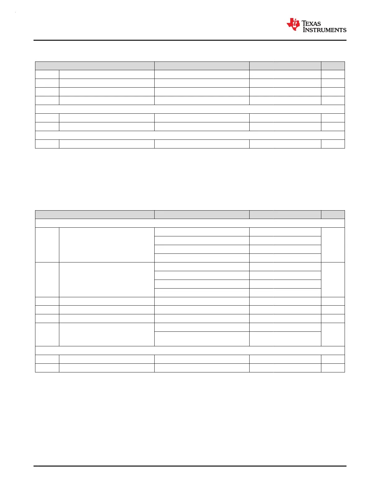
7.9.4 Low Frequency Crystal/Clock (continued)
over operating free-air temperature range (unless otherwise noted)
PARAMETER TEST CONDITIONS MIN TYP MAX UNIT
OA
LFXT
LFXT crystal oscillation allowance 200 kΩ
C
L, eff
Integrated effective load capacitance
(1)
1 pF
t
start, LFXT
LFXT start-up time 1000 ms
I
LFXT
LFXT current consumption XT1DRIVE=0, LOWCAP=1 200 nA
Low frequency digital clock input (LFCLK_IN)
f
LFIN
LFCLK_IN frequency
(2)
SETUSEEXLF=1 29491 32768 36045 Hz
DC
LFIN
LFCLK_IN duty cycle
(2)
SETUSEEXLF=1 40 60 %
LFCLK Monitor
f
FAULTLF
LFCLK monitor fault frequency
(3)
MONITOR=1 2800 4200 8400 Hz
(1) This includes parasitic bond and package capacitance (≈2pF per pin), calculated as C
LFXIN
×C
LFXOUT
/(C
LFXIN
+C
LFXOUT
), where C
LFXIN
and C
LFXOUT
are the total capacitance at LFXIN and LFXOUT, respectively.
(2) The digital clock input (LFCLK_IN) accepts a logic level square wave clock.
(3) The LFCLK monitor may be used to monitor the LFXT or LFCLK_IN. It will always fault below the MIN fault frequency, and will never
fault above the MAX fault frequency.
7.9.5 High Frequency Crystal/Clock
over operating free-air temperature range (unless otherwise noted)
PARAMETER TEST CONDITIONS MIN TYP MAX UNIT
High frequency crystal oscillator (HFXT)
f
HFXT
HFXT frequency
HFXTRSEL=00 4 8
MHz
HFXTRSEL=01 8.01 16
HFXTRSEL=10 16.01 32
HFXTRSEL=11 32.01 48
DC
HFXT
HFXT duty cycle
HFXTRSEL=00 40 65
%
HFXTRSEL=01 40 60
HFXTRSEL=10 40 60
HFXTRSEL=11 40 60
OA
HFXT
HFXT crystal oscillation allowance HFXTRSEL=00 (4 to 8MHz range) 2 kΩ
C
L, eff
Integrated effective load capacitance
(1)
1 pF
t
start, HFXT
HFXT start-up time
(2)
HFXTRSEL=11, 32MHz crystal 0.5 ms
I
HFXT
HFXT current consumption
(2)
f
HFXT
=4MHz, R
m
=300Ω, C
L
=12pF 75
uA
f
HFXT
=48MHz, R
m
=30Ω, C
L
=12pF,
C
m
=6.26fF, L
m
=1.76mH
600
High frequency digital clock input (HFCLK_IN)
f
HFIN
HFCLK_IN frequency
(3)
USEEXTHFCLK=1 4 48 MHz
DC
HFIN
HFCLK_IN duty cycle
(3)
USEEXTHFCLK=1 40 60 %
(1) This includes parasitic bond and package capacitance (≈2pF per pin), calculated as C
HFXIN
×C
HFXOUT
/(C
HFXIN
+C
HFXOUT
), where C
HFXIN
and C
HFXOUT
are the total capacitance at HFXIN and HFXOUT, respectively.
(2) The HFXT startup time (t
start, HFXT
) is measured from the time the HFXT is enabled until stable oscillation for a typical crystal. Start-up
time is dependent upon crystal frequency and crystal specifications. Refer to the HFXT section of the MSPM0 G-Series 80-MHz
Microcontrollers Technical Reference Manual.Current consumption increases with higher RSEL and start up time is decreases with
higher RSEL.
(3) The digital clock input (HFCLK_IN) accepts a logic level square wave clock.
MSPM0G3507, MSPM0G3506, MSPM0G3505
SLASEX6A – FEBRUARY 2023 – REVISED JUNE 2023
www.ti.com
36 Submit Document Feedback
Copyright © 2023 Texas Instruments Incorporated
Product Folder Links: MSPM0G3507 MSPM0G3506 MSPM0G3505