TRST
TMS
TCK
TDI
TDO
RTCK
ICEPICK_C
BoundaryScan
BSR/BSDL
BoundaryScanI/F
SecondaryTap0
DAP
Debug APB
Debug
ROM1
APBslave
Cortex
R4F
APBMux
AHB-AP
POM
toSCR1via A2A
from
PCR1/Bridge
TestTap0
eFuseFarm
SecondaryTap2
AJSM
TestTap1
PSCON
RM46L852
SPNS185 –SEPTEMBER 2012
www.ti.com
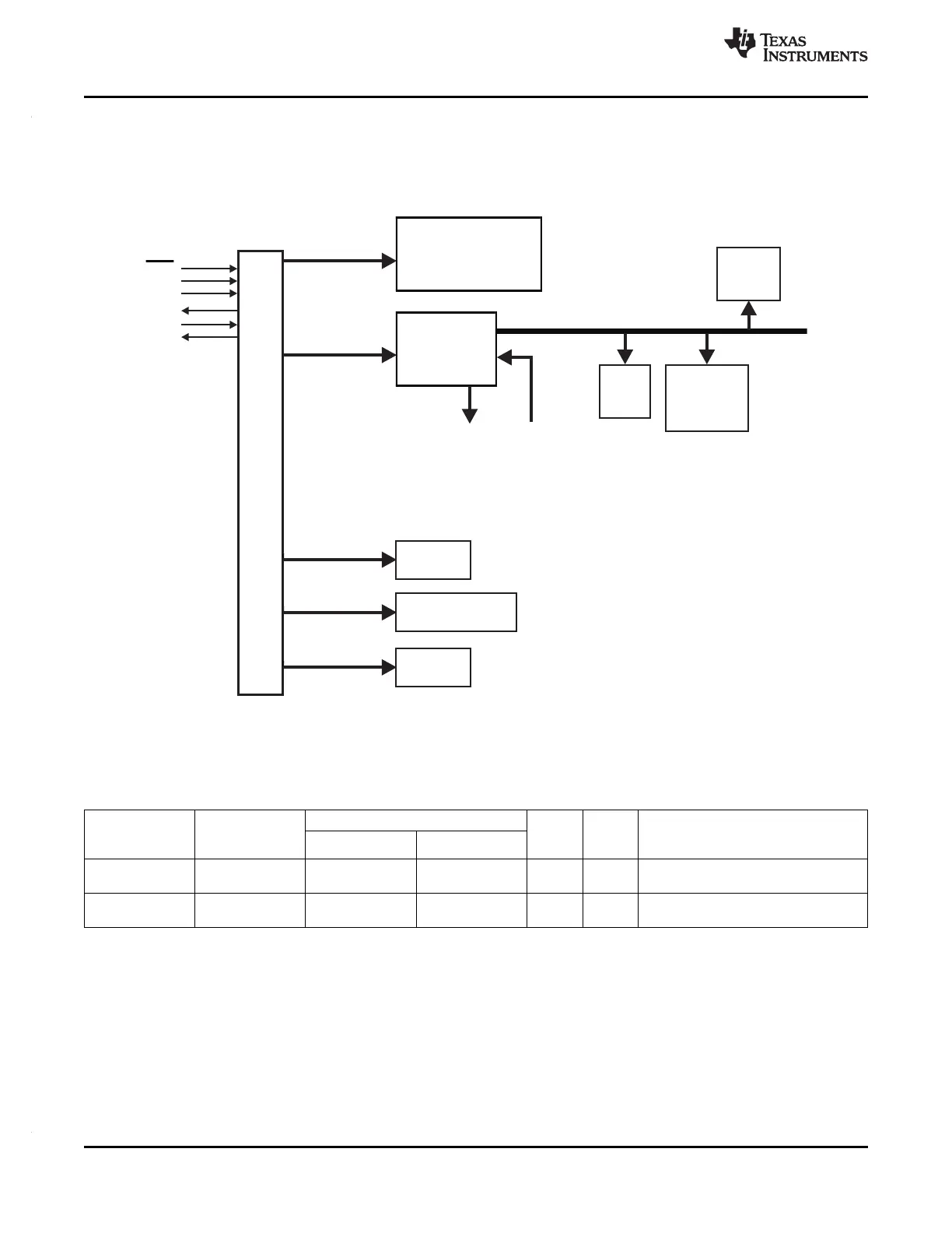
4.21 Debug Subsystem
4.21.1 Block Diagram
The device contains an ICEPICK module to allow JTAG access to the scan chains.
Figure 4-20. Debug Subsystem Block Diagram
4.21.2 Debug Components Memory Map
Table 4-38. Debug Components Memory Map
FRAME ADDRESS RANGE RESPNSE FOR ACCESS TO
FRAME CHIP FRAME ACTUA
MODULE NAME UNIMPLEMENTED LOCATIONS IN
SELECT SIZE L SIZE
START END
FRAME
CoreSight Debug Reads return zeros, writes have no
CSCS0 0xFFA0_0000 0xFFA0_0FFF 4kB 4kB
ROM effect
Cortex-R4F Reads return zeros, writes have no
CSCS1 0xFFA0_1000 0xFFA0_1FFF 4kB 4kB
Debug effect
4.21.3 JTAG Identification Code
The JTAG ID code for this device is 0x0B95502F. This is the same as the device ICEPick Identification
Code.
4.21.4 Debug ROM
The Debug ROM stores the location of the components on the Debug APB bus:
112 System Information and Electrical Specifications Copyright © 2012, Texas Instruments Incorporated
Submit Documentation Feedback