OSCIN
OSCOUT
C1
(see Note A)
C2
Crystal
(a)
OSCIN OSCOUT
(b)
External
(toggling 0-3.3V)
Clock Signal
Note A: The values of C1 and C2 should be provided by the resonator/crystal vendor.
Kelvin_GND
Note B: Kelvin_GND should not be connected to any other GND.
(see Note B)
RM46L852
SPNS185 –SEPTEMBER 2012
www.ti.com
4.6 Clocks
4.6.1 Clock Sources
The table below lists the available clock sources on the device. Each of the clock sources can be enabled
or disabled using the CSDISx registers in the system module. The clock source number in the table
corresponds to the control bit in the CSDISx register for that clock source.
The table also shows the default state of each clock source.
Table 4-8. Available Clock Sources
Clock
Name Description Default State
Source #
0 OSCIN Main Oscillator Enabled
1 PLL1 Output From PLL1 Disabled
2 Reserved Reserved Disabled
3 EXTCLKIN1 External Clock Input #1 Disabled
4 LFLPO Low Frequency Output of Internal Reference Oscillator Enabled
High Frequency Output of Internal Reference
5 HFLPO Enabled
Oscillator
6 PLL2 Output From PLL2 Disabled
7 EXTCLKIN2 External Clock Input #2 Disabled
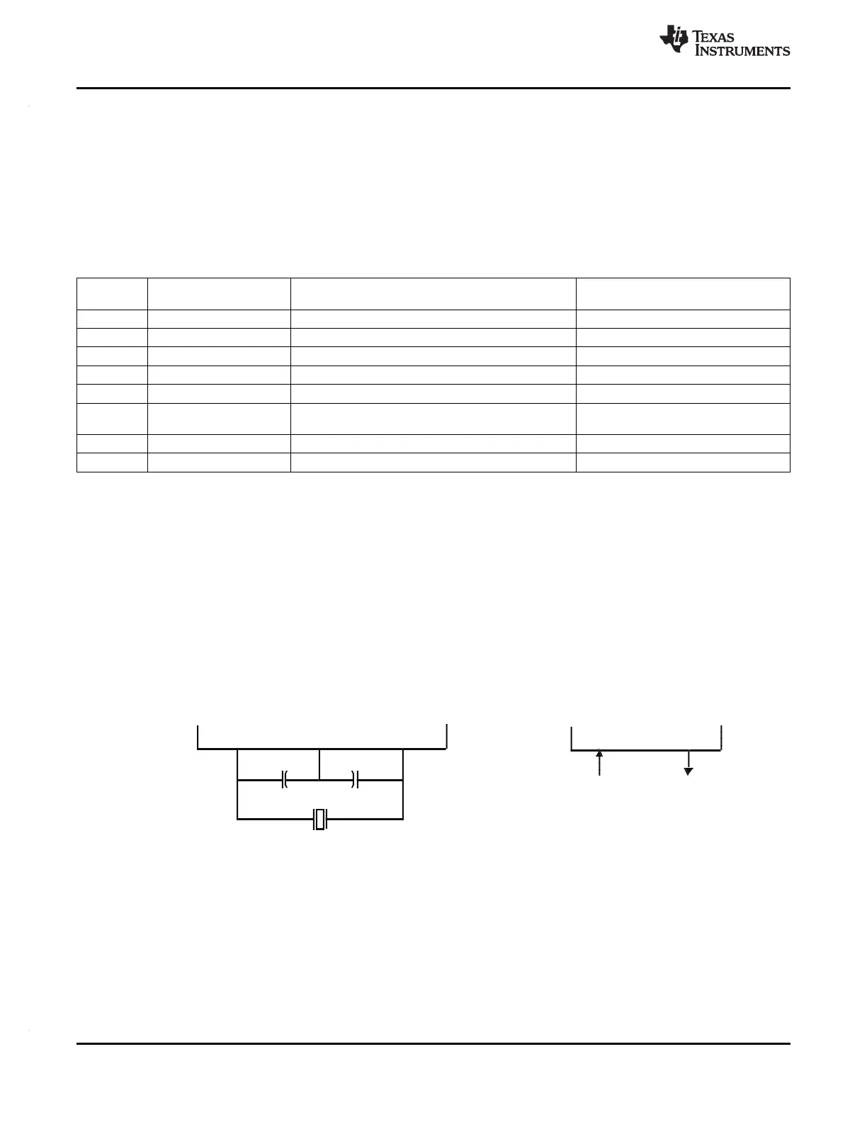
4.6.1.1 Main Oscillator
The oscillator is enabled by connecting the appropriate fundamental resonator/crystal and load capacitors
across the external OSCIN and OSCOUT pins as shown in Figure 4-4. The oscillator is a single stage
inverter held in bias by an integrated bias resistor. This resistor is disabled during leakage test
measurement and low power modes.
TI strongly encourages each customer to submit samples of the device to the resonator/crystal
vendors for validation. The vendors are equipped to determine what load capacitors will best tune
their resonator/crystal to the microcontroller device for optimum start-up and operation over
temperature/voltage extremes.
An external oscillator source can be used by connecting a 3.3V clock signal to the OSCIN pin and leaving
the OSCOUT pin unconnected (open) as shown in the figure below.
Figure 4-4. Recommended Crystal/Clock Connection
62 System Information and Electrical Specifications Copyright © 2012, Texas Instruments Incorporated
Submit Documentation Feedback