RM46L852
SPNS185 –SEPTEMBER 2012
www.ti.com
4.4 Warm Reset (nRST)
This is a bidirectional reset signal. The internal circuitry drives the signal low on detecting any device reset
condition. An external circuit can assert a device reset by forcing the signal low. On this terminal, the
output buffer is implemented as an open drain (drives low only). To ensure an external reset is not
arbitrarily generated, TI recommends that an external pullup resistor is connected to this terminal.
This terminal has a glitch filter. It also has an internal pullup
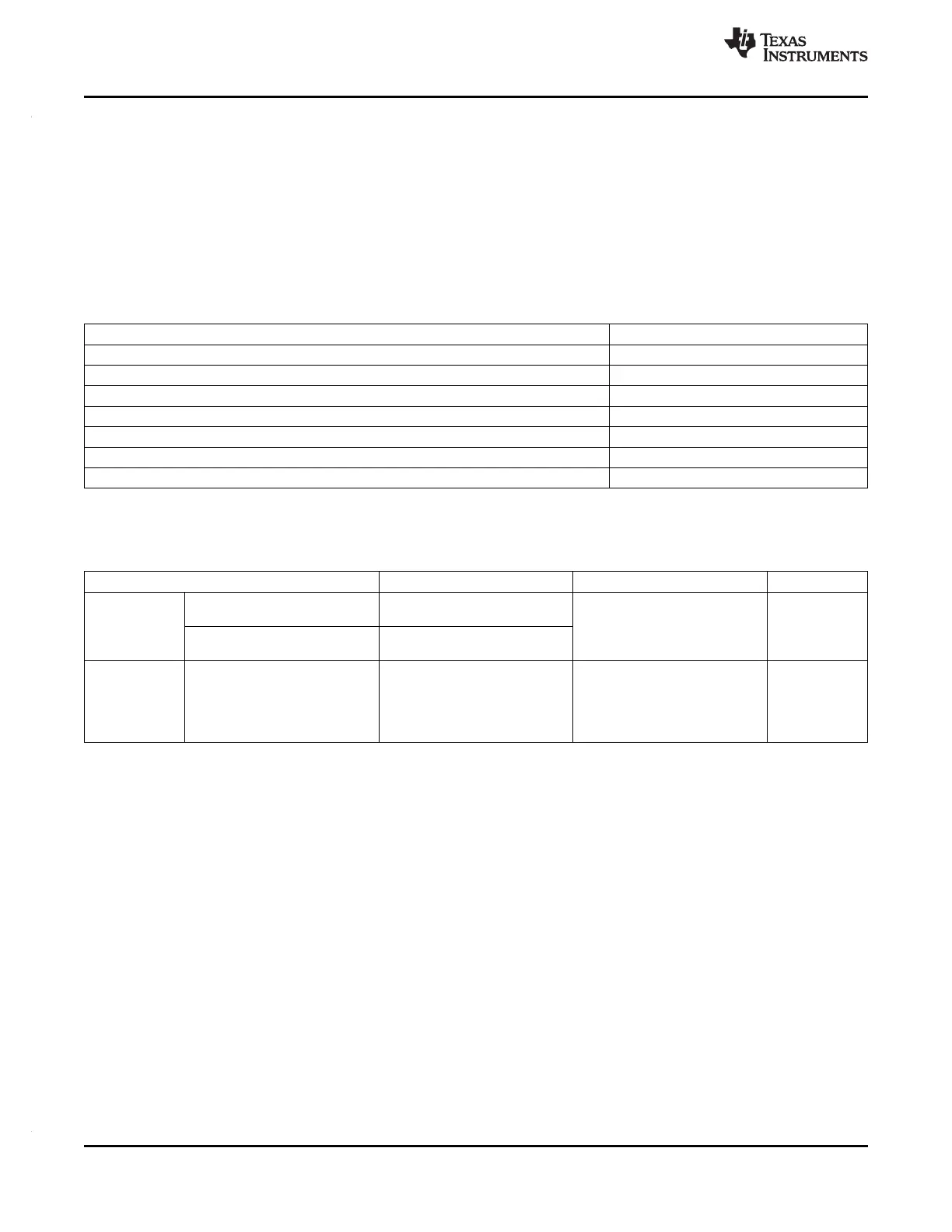
4.4.1 Causes of Warm Reset
Table 4-5. Causes of Warm Reset
DEVICE EVENT SYSTEM STATUS FLAG
Power-Up Reset Exception Status Register, bit 15
Oscillator fail Global Status Register, bit 0
PLL slip Global Status Register, bits 8 and 9
Watchdog exception / Debugger reset Exception Status Register, bit 13
CPU Reset (driven by the CPU STC) Exception Status Register, bit 5
Software Reset Exception Status Register, bit 4
External Reset Exception Status Register, bit 3
4.4.2 nRST Timing Requirements
Table 4-6. nRST Timing Requirements
(1)
PARAMETER MIN MAX UNIT
t
v(RST)
Valid time, nRST active after 1160 t
c(OSC)
+ 1048t
c(OSC)
ns
nPORRST inactive
Valid time, nRST active (all other 8t
c(VCLK)
System reset conditions)
t
f(nRST)
500 2000 ns
Filter time nRST pin;
pulses less than MIN will be
filtered out, pulses greater than
MAX will generate a reset
(1) Specified values do NOT include rise/fall times. For rise and fall timings, see Table 3-4.
58 System Information and Electrical Specifications Copyright © 2012, Texas Instruments Incorporated
Submit Documentation Feedback