AS 680/682
Description, Operation and Maintenance Technical Situation Display
ADS−B
4−29Ed. 10.07
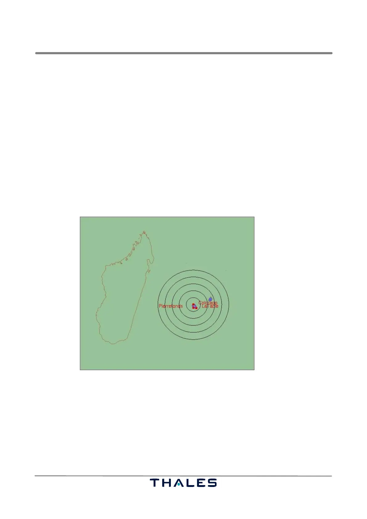
4.4.5 Map View
The map view, see Fig. 4−46, of the Technical Situation Display shows an environment of a Ground
Station. The map’s co−ordination system can be a cartesian or a spherical one. The used vector
maps are found in files with the extension .reg.
S The cartesian co−ordination system needs a map, whose components are given in cartesian co−
ordinates in the unit meters, where the origin of the reference system is the position of the Ground
Station. The position of the Ground Station must be given in the configuration file in longitude /
latitude values.
S The spherical maps use longitude and latitude values. Spherical maps don’t need a reference
point, they take the global WGS 84 reference system. For representation in the map view, the Miller
projection (a world projection) is applied to the spherical maps. The ADS−B applications use
spherical maps.
The colors of the map components can be chosen in the configuration file. It is possible to show/hide
components and to configure the representation of the target plots referring to sections 4.4.2.2 to
4.4.2.5.
Fig. 4−46 TSD, Map view (example)
4.4.5.1 Map View Features
The following actions are provided for the map view:
S Zooming:
It is possible to zoom into the map, to zoom out of the map or to reset the original view by using
the tools of the toolbar (see section 4.4.3) or the corresponding keys ‘Alt −’ or ‘Alt +‘ or ‘Alt r’.
It is possible to zoom into a rectangle by holding the left mouse button pressed and dragging the
mouse. It is possible to zoom in or out by using the scroll wheel of the mouse. Endless zooming
is not applicable. There are upper and lower bounds.
 Loading...