CUTMASTER 152
Manual 0-4987 3-3 INSTALLATION
3.04 Gas Connections
Connecting Gas Supply to Unit
The connection is the same for compressed air or
high pressure cylinders. Refer to the following
two subsections if an optional air line lter is to
be installed.
1. Connect the air line to the inlet port. The
illustration shows typical ttings as an
example.
NOTE
For a secure seal, apply thread sealant to the
fitting threads, according to manufacturer's
instructions. Do not use Teflon tape as a thread
sealer, as small particles of the tape may break
off and block the small air passages in the torch.
Art # A-07943
Hose Clamp
Assembly
Inlet Port
Gas Supply
Hose
1/4 NPT or ISO-R
to 1/4” (6mm) Fitting
Air Connection to Inlet Port
Installing Optional Single - Stage Air Filter
An optional lter kit is recommended for im-
proved ltering with compressed air, to keep
moisture and debris out of the torch.
1. Attach the Single - Stage Filter Hose to the
Inlet Port.
2. Attach the Filter Assembly to the lter
hose.
3. Connect the air line to the Filter. The
illustration shows typical ttings as an
example.
NOTE
For a secure seal, apply thread sealant to the
fitting threads, according to the maker's instruc-
tions. Do Not use Teflon tape as a thread sealer,
as small particles of the tape may break off and
block the small air passages in the torch. Con-
nect as follows:
Art # A-07944
Hose Clamp
1/4 NPT to 1/4"
(6mm) Fitting
Assembly
Inlet Port
Gas Supply
Hose
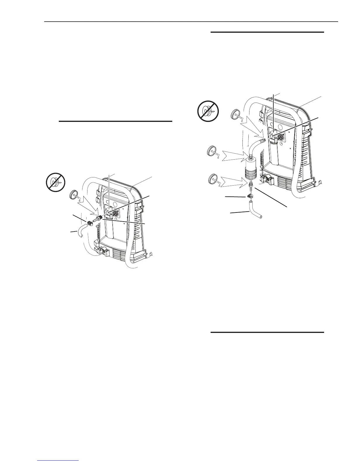
Optional Single - Stage Filter Installation
Installing Optional Two - Stage Air Filter Kit
This optional two - stage air line lter is also
for use on compressed air shop systems. Filter
removes moisture and contaminants to at least 5
microns.
Connect the air supply as follows:
1. Attach the Two Stage Filter bracket to the
back of the power supply per instructions
supplied with the lter assembly.
NOTE
For a secure seal, apply thread sealant to the fit-
ting threads according to manufacturer's instruc-
tions. Do Not use Teflon tape as a thread sealer
as small particles of the tape may break off and
block the small air passages in the torch.
2. Connect the two stage lter outlet hose to
the inlet port of the Regulator / Filter As-
sembly.
3. Use customer - supplied ttings to connect
the air line to the Filter. A 1/4 NPT to 1/4"
hose barbed tting is shown as an example.