TROUBLESHOOTING 4-6 Manual 0-2898
K. AC indicator steady ON: TEMP indicator ON;
RUN/SET switch in SET position
1. PC board temperature sensor disconnected or faulty.
a. Check wire harness connection at terminal J5
on PC board. Reconnect if necessary.
b. Disconnect PC board temperature sensor wire
harness from J5 on PC board. Install a tempo-
rary jumper across the pins on PC board termi-
nal J5. Check temperature indicator on Power
Supply front panel. If TEMP indicator is OFF,
replace PC board.
L. No gas flow; AC indicator ON; GAS indicator
OFF; TEMP indicator OFF; DC indicator OFF;
RUN/SET switch in SET position
1. Gas supply not connected to unit
a. Connect gas supply.
2. Gas supply not turned on
a. Turn gas supply on.
3. Gas pressure too low
a. Shut power supply off. Set gas pressure on the
power supply gas regulator to 65 psi / 4.5 bar.
turn power supply back on.
4. Faulty PC board
a. Disconnect pressure switch wire harness from
terminal J9 on PC board. Test for continuity
between sockets 2 and 3 on the wire harness
connector. If gas pressure is above 65 psi / 4.5
bar and there is continuity between sockets 2
and 3, replace PC board.
4.08 Pilot Arc Problems
Locate your symptom below:
A. No pilot arc; Gas flows continuously; AC indica-
tor ON; TEMP indicator OFF; GAS indicator ON;
DC indicator OFF
1. Shorted Torch
a. Test torch and leads for continuity.
2. Faulty PC Board
a. Replace PC Board.
B. No arc or intermittent arc in torch; Gas flows; AC
indicator ON; TEMP indicator OFF; GAS and DC
indicators ON
1. Gas pressure set incorrectly (too high)
a. Set gas pressure on the Power Supply gas regu-
lator to 65 psi / 4.5 bar.
2. Oil/moisture in air lines
a. Purge system. If problem is corrected, add fil-
ters in line with air source.
3. Torch consumable parts incorrect or worn
a. Refer to Operator's Manual.
4. Starter cartridge missing from torch
a. Shut off power. Remove shield cup from torch.
Install starter cartridge if missing.
5. Faulty leads
a. Check continuity.
6. Faulty torch
a. Check continuity.
7. Faulty PC Board
a. Replace PC Board.
C. No pilot arc; GAS and DC indicators blink
1. Gas pressure is too low.
a. Set gas pressure to 65 psi / 4.5 bar.
D. No gas flow; AC and GAS indicators ON, TEMP
and DC indicators OFF
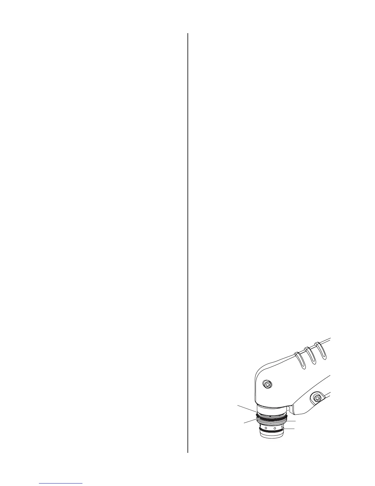
1. Upper O-ring on torch head is in wrong position.
a. Remove shield cup from torch; check position
of upper O-ring. Correct if necessary.
Lower O-Ring
Upper O-Ring
in Correct Groove
Upper Groove
with Vent Holes
Must Remain Open
Threads
Art # A-03640
 Loading...


