SERVICE 5-4 Manual 0-2898
7. Secure the diode bridge to the Fan Panel with the
hardware removed previously. Torque the hard-
ware to 15 in-lbs (1.7 Nm).
8. Apply RTV silicone over the securing hardware.
Use care to avoid getting RTV on the electrical con-
nectors.
9. Refer to the illustration. Connect wires from the
PC Board to the diode bridge(s) being replaced.
10. Reinstall the Power Supply cover. Test the Power
Supply for proper operation.
5.07 Rear Panel Parts Replacement
Refer to Section 6 for parts list and overall detailed draw-
ing.
WARNING
Disconnect input power at the source and bleed
down the system before attempting these proce-
dures.
A. Pressure Gauge Replacement
1. Disconnect the gas input line from the Power Supply.
2. Remove the Power Supply cover per Subsection
5.04-A.
3. Disconnect the gas tube from the Pressure Switch
Assembly Adapter Fitting. Hold a wrench or simi-
lar tool against the locking ring on the Fitting and
pull the tube to release it.
4. Disconnect the Filter/Regulator Assembly as fol-
lows:
a. Pull the Regulator/Filter drain tube out of the
hole in the base of the Power Supply.
b. Release the securing ring on the top of the
Regulator/Filter Assembly.
c. Move the Regulator/Filter Assembly forward
to disengage the inlet port and pressure gauge
from the Power Supply rear panel.
5. Turn the Pressure Gauge to release it from the
Regulator/Filter Assembly.
6. Apply thread sealant to the threads of the replace-
ment Pressure Gauge.
NOTE
Do Not use Teflon tape as a thread sealer, as small
particles of the tape may break off and block the
small gas passages in the torch.
7. Thread the replacement Pressure Gauge into the
Power Supply the Regulator/Filter Assembly.
Tighten securely.
8. Position the Regulator/Filter Assembly in the
bracket at the top of the Power Supply. Secure
with the locking ring.
9. Connect the gas tube to the Pressure Switch As-
sembly Adapter Fitting. Push in the Fitting, and
insert the gas tube. Release the Fitting. The fitting
will automatically lock. Check for a secure con-
nection.
10. Position the bottom end of the drain tube in the
hole in the Power Supply base.
11. Reinstall the Power Supply cover. Connect the gas
input line to the inlet port. Connect the Power Sup-
ply to primary input power.
12. Test the Power Supply for proper operation.
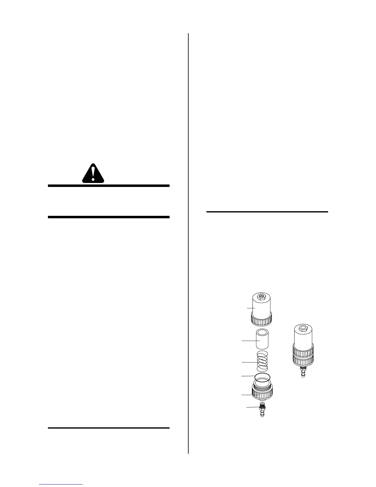
C. Optional Single-Stage Filter Element
Replacement
NOTES
The Power Supply shuts down automatically when
the Filter Element becomes completely saturated.
The Filter Element can be removed from its hous-
ing, dried, and reused. Allow 24 hours for Ele-
ment to dry.
1. Remove power from power supply.
2. Disconnect gas supply hose.
Art # A-02476
Filter
Element
(Cat. No. 9-7741)
Housing
Cover
Barbed
Fitting
Spring
Assembled Filter
O-ring
(Cat. No. 9-7743)
 Loading...


