Manual 0-2898 4-7 TROUBLESHOOTING
4.09 Main Arc Problems
Locate your symptom below:
A. Main cutting arc will not start
1. Work cable not connected.
a. Connect work cable.
2. Holding too high of a standoff
a. Refer to Operating Manual for recommended
standoff heights.
3. Workpiece is painted or rusty.
a. Clean workpiece.
4. Starter cartridge missing from torch
a. Shut off power. Remove shield cup from torch.
Install starter cartridge if missing.
5. Faulty Main Power PC Board
a. Replace PC Board.
4.10 Test Procedures
The test procedures in this subsection are referenced in
the troubleshooting section.
A. Safety Precautions
1. Significant DC Voltage exists after removal of input
power. Allow two minutes for discharge time. Volt-
age measured on input capacitors must be zero be-
fore performing service on the power supply.
2. Do Not touch electrical components with any part of
the human body when power is applied.
3. Keep away from any moving parts.
4. Hot surfaces can cause severe burns. Allow equip-
ment to cool before servicing.
5. Electrostatic discharge can damage printed circuit
board assemblies. Transport printed circuit boards in
proper antistatic shielded packages. Use proper
grounding techniques with wrist strap before handling
printed circuit boards.
6. Misaligned plugs can cause printed circuit board dam-
age. Be sure plugs are properly aligned and com-
pletely seated.
7. Excessive pressure can damage printed circuit board.
Use only minimal pressure and gentle movement
when disconnecting or connecting printed circuit
board plugs.
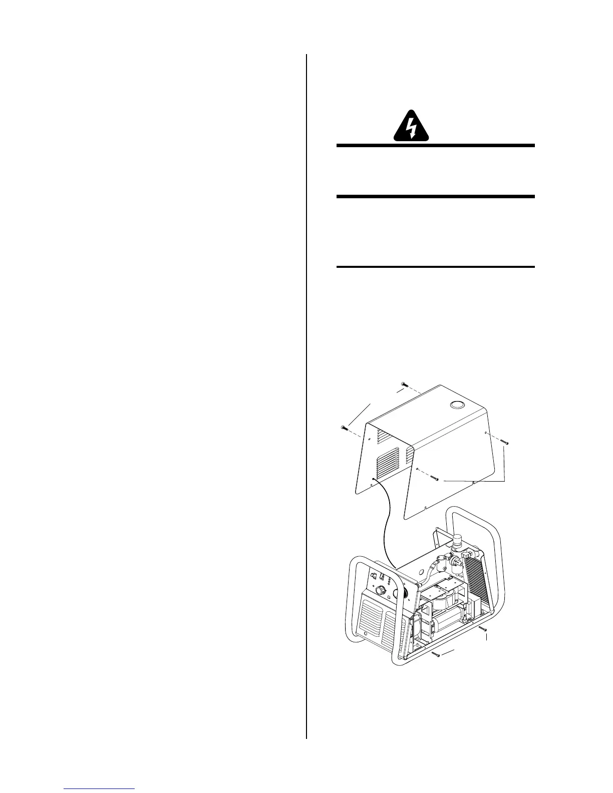
B. Opening Power Supply Enclosure
The cover of the Power Supply must be removed to gain
access to the input power connections.
WARNING
Disconnect primary power at the source before as-
sembling or disassembling the Power Supply, torch
parts, or torch and leads assemblies.
1. Remove the upper screws securing the cover to the
main assembly.
2. Loosen, but do not remove, the lower screws.
NOTE
There is a ground wire attached from the cover to
the main body of the unit.
3. Carefully lift the cover off the unit, and remove the
nut securing the ground wire to the side panel.
4. Reinstall the cover by reversing the above steps.
Upper screws
Ground
wire
Lower screws
Upper screws
A-03285

 Loading...


