TROUBLESHOOTING 4-8 Manual 0-2898
C. Diode Testing Basics
Testing of diode modules requires a digital volt/ohm-
meter that has a diode test scale. Remember that even
if the diode module checks good, it may still be bad.
If in doubt, replace the diode module.
1. Locate the diode module to be tested.
2. Remove cables from mounting studs on diodes to iso-
late the module.
3. Set digital volt/ohmmeter to diode test scale.
4. Using the Figures for each test, check each diode in
the module. Each diode must be checked in forward
bias (plus to negative) and reverse bias (negative to
plus) direction.
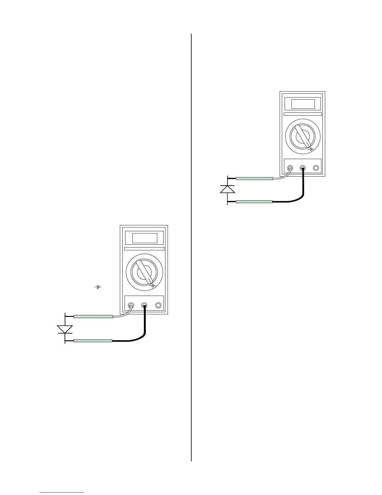
5. Connect the volt/ohmmeter positive lead to the an-
ode (+) of the diode and the negative lead to the cath-
ode (-) of the diode for forward bias testing (refer to
following figure). A properly functioning diode will
conduct in the forward bias direction and indicate be-
tween 0.3 to 0.9 volts.
0.75
VR
COM
A
Art # A-00307
Anode
Cathode
Forward Bias
Diode Conducting
+
_
Diode Test Symbol
Testing Diode Forward Bias
6. Reverse the meter leads across the diode for reverse
bias testing (refer to following figure). A properly
functioning diode will block in the reverse bias direc-
tion and depending on the meter function will indi-
cate an open or “OL”.
OL
VR
COM
A
Art # A-00306
Anode
Cathode
Reverse Bias
Diode Not Conducting
+
_
Testing Diode Reverse Bias
 Loading...


