SERVICE 5-2 Manual 0-2898
5.04 Major External Parts
Replacement
Refer to Section 6 for Major External Replacement Parts
and overall detailed drawing.
WARNING
Disconnect primary power from the source before
opening or disassembling the power supply.
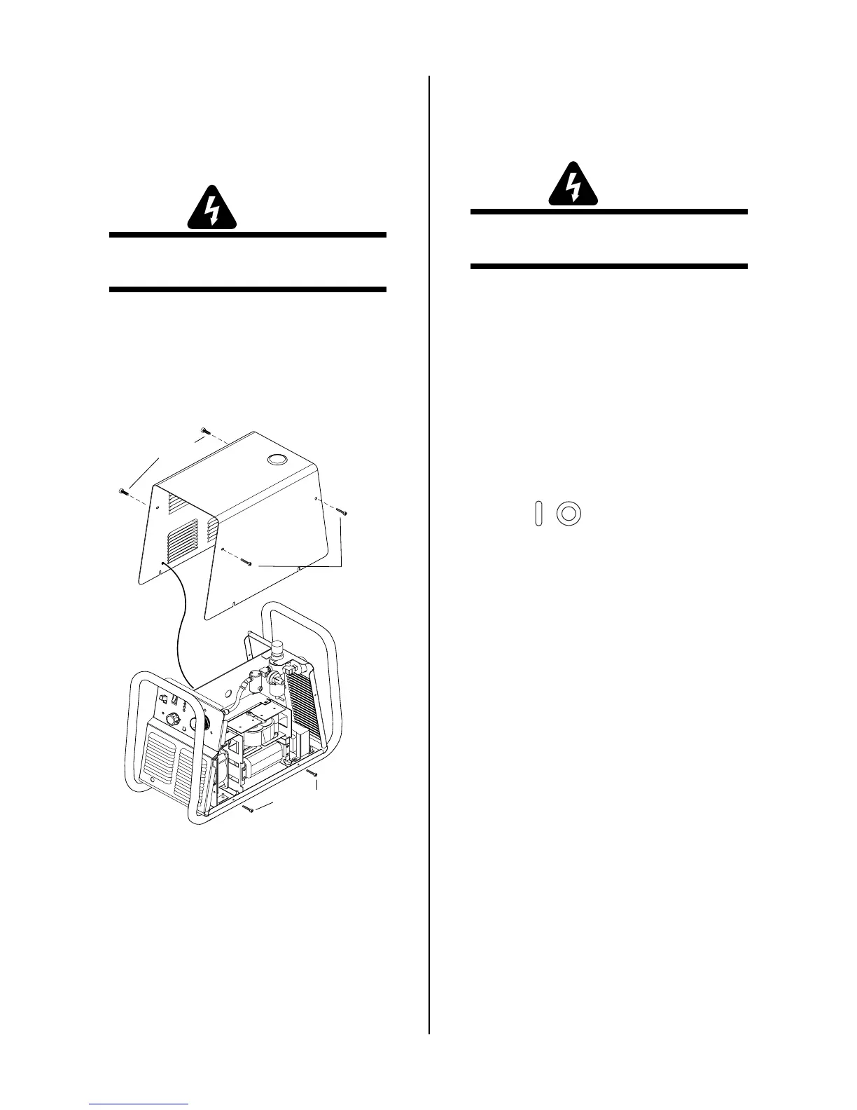
A. Cover Removal and Replacement
1. Remove the upper screws securing the cover to
the unit then loosen the lower screws securing the
cover to the base.
Upper screws
Ground
wire
Lower screws
Upper screws
A-03285
2. Carefully lift the cover up and away from the unit
to gain access to the ground wire connection on
the inside of the cover (left side near front).
3. Remove the nut and washer from the ground stud
on the inside of the cover.
4. Install the replacement cover by reversing the above
steps.
5.05 Front Panel Parts Replacement
Refer to Section 6 for Front Panel Replacement Parts and
overall detailed drawing.
WARNING
Disconnect primary power from the source before
opening or disassembling the power supply.
A. Output Control (A) Knob Replacement
1. Turn the adjustment knob fully clockwise and note
the location of the pointer on the knob.
2. Loosen the screw securing the Knob to the poten-
tiometer shaft and remove the Knob.
3. Place the replacement Knob on the potentiometer
shaft with the location of the pointer the same as
noted in step 1.
4. Tighten the screw to secure the knob to the poten-
tiometer shaft.
B. ON/OFF ( / ) Switch Replacement
1. Remove the cover per Subsection 5.04-A.
2. Disconnect wires E1 and E2 leading from the
switch to terminals E1 and E2 on the PC Board.
3. Remove the hardware securing the switch to the
Power Supply front panel.
4. Note the positions of the wires from the input
power cable to the switch.
5. Disconnect the input power cable from the switch.
6. Connect the input power cable to the replacement
switch, with the wires positioned as noted previ-
ously.
7. Transfer wires E1 and E2 to the replacement
switch.
8. Attach the replacement Switch to the Power Sup-
ply front panel. Tighten the hardware securely.
9. Connect wires E1 and E2 to terminals E1 and E2
on the PC Board.
10. Reinstall the Power Supply cover.
11. Connect the Power Supply to primary input power.
Test the Power Supply for proper operation.

 Loading...


