Manual 0-2898 5-3 SERVICE
C. Run/Set ( / ) Switch
Replacement
1. Remove the Power Supply cover per Subsection
5.04-A.
2. Disconnect the Run/Set Switch wire harness from
terminal J2 on the PC Board.
3. Squeeze together the clips on the rear of the
Switch, then remove the switch and wire harness
through the Front Panel.
4. Transfer the wiring harness to the replacement
switch. Refer to the illustration for wire connec-
tions.
A-03493
Wire # 8
Wire # 9
Top clip
5. Pass the wiring harness through the front opening
in the Power Supply. Press the switch into posi-
tion in the Power Supply front panel firmly.
6. Connect the wiring harness to terminal J2 on the
PC Board.
7. Reinstall the Power Supply cover.
8. Connect the Power Supply to primary input power.
Test the Power Supply for proper operation.
5.06 Left Side Internal Parts
Replacement
Refer to Section 6 Left Side Internal Replacement Parts.
WARNING
Disconnect input power at the source and bleed
down the system before attempting these proce-
dures.
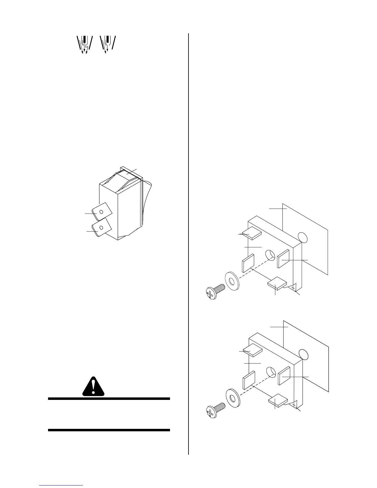
A. Diode Bridge Replacement
1. Remove the Power Supply cover per Subsection
5.04-A.
2. Label and remove the wires from the diode bridge
to the PC Board. Refer to the illustration.
3. Remove RTV silicone over the screw head secur-
ing the diode bridge to the Fan Panel.
4. Remove hardware securing the diode bridge to the
Fan Panel.
5. Remove the diode bridge.
6. Refer to the illustration. Position the diode bridge
as shown. Note the location of the notched area
marked (+) on the diode bridge. Position the re-
placement diode bridge on the thermal pad on the
Fan Panel. Replace the thermal pad if it is dam-
aged.
+ Mark
E15B
E12B
A-03494
E16B
E14B
+ Mark
E16A
E15A
E14A
E12A
+ Mark
Diode Bridge 2
E15B
E12B
E16B
E14B
Thermal Pad
Thermal Pad
Diode Bridge 1
 Loading...


