Manual 0-2898 A-7 APPENDIX
5
5
6
6
7
7
8
8
9
9
10
10
A
B
C
D
E
F
SOL1
J3
1
22
TORCH
SWITCH
2
(13)
P1
1
J1
T
3
(12)
WORK
P3
1
O
A
GAS SOLENOID
C
H
1
1
B
R
4
2
COMP DESCRIPTION
SW1
SW2
M1 FAN, 4.5" 12VDC
D2
PS1 PRESSURE SWITCH
SOL1 GAS SOLENOID
SWITCH, ON/OFF
SWITCH, RUN/SET
T3
TS1
GCW
OVER-TEMP. SENSOR
L1 OUTPUT INDUCTOR
MAIN TRANSFORMER
L1
OUTPUT INDUCTOR
D22
D99
TORCH SWITCH ON
PWM ON
+14VA
AGND
+12VB
BGND
T3
SEC
PRI
MAIN
TORCH
PILOT
WORK
44
3
3
PIP
C1
D1
D9
A8
A7
B2
D1
PFC INDUCTOR
T1
(E8)
(14)
(15)
o
o
P8J8
4
3
1
2
QUICK DISCONNECT
5
(E4)
(-)
REL ECO 100213
GCW
7/29/02
AA
42X1089
Thursday, March 20, 2003
11
INDUSTRIAL PARK No. 2
WEST LEBANON, NH 03784
603-298-5711
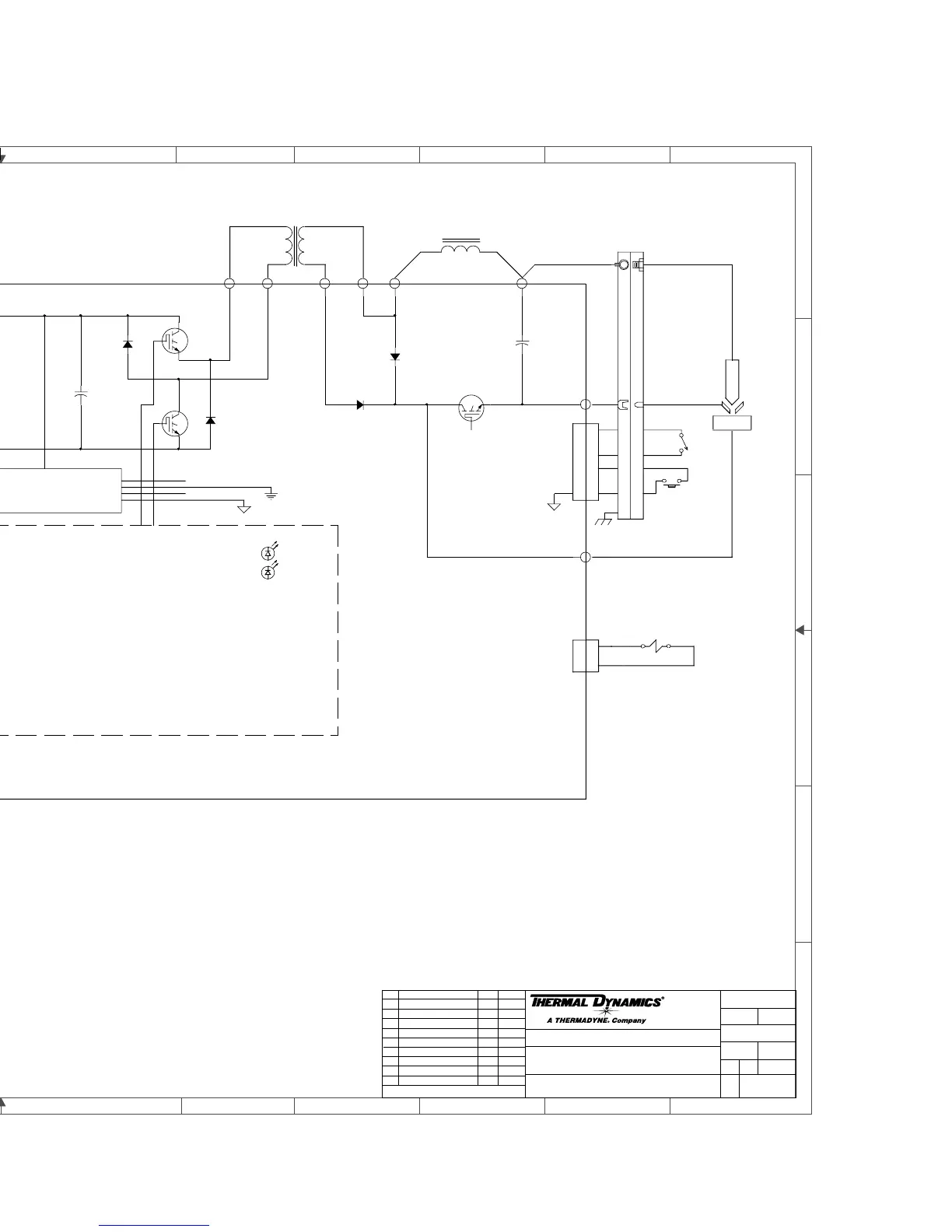
CM38 120/208/230V SINGLE PHASE 50/60 Hz
Tuesday, May 15, 2001
15:05:29
THERMAL DYNAMICS
C
DWG No:
Sheet
of
SupersedesScale
Date:
Drawn: References
DateByRevisionsRev
PCB No:
Assy No:
Information Proprietary to THERMAL DYNAMICS CORPORATION.
Not For Release, Reproduction, or Distribution without Written Consent.
NOTE:
Unless Otherwise Specified, Resistors are in Ohms 1/4W 5%.
Capacitors are in Microfarads (UF)
Chk: App:
TITLE:
Last Modified:
Size
SCHEMATIC,
E4
E5
D55
E10
E19
Q11
E20
D53
C70, 72, 81
C71, 73, 75
E8
E9
Q13
D54
E6
D56
Q12
A-03405
REL ECO 100333
GCW
10/04/02
AB
REL ECO 100535
DAT
2/27/03
A
C
2
A4
LOCATION
 Loading...


