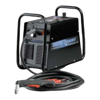
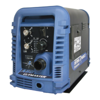
cutmaster 39
Manual 0-4976 4-7 OPERATION
4.03 Sequence of Operation
The following is a typical sequence of operation for this power supply. Refer to Appendix 1 for block
diagram.
1. Plug the input power cord into an active circuit.
a. AC power is available at the Power Supply.
2. Place the ON / OFF switch on the Power Supply to ON (up) position.
a. AC indicator turns on; fan turns on.
NOTES
If there is adequate gas supply pressure to the power supply, gas comes on if Torch Trigger is pressed.
If torch trigger is held while user turns on main AC power, system goes into 'protective interlock' mode. AC
indicator flashes; torch will not pilot. Release torch trigger, turn AC switch OFF then ON.
3. Put RUN / SET switch to SET (down position).
a. Gas ows to set pressure. Turn gas pressure adjustment knob to set pressure to 65 psi / 4.5
bar; Gas indicator turns ON when there is sufcient gas pressure for power supply opera-
tion.
NOTE
Minimum pressure for power supply operation is lower than minimum pressure for torch operation.
4. Put RUN / SET switch to RUN (up position). Gas ow stops.
5. Wear protective clothing and welding gloves. Protect eyes. Slide the trigger release to the rear;
squeeze and hold the trigger. Gas ows briey, then shuts off momentarily. Then gas ow will
resume. Pilot arc is established. DC indicator turns ON. Move Torch within transfer dis-
tance of workpiece.
a. Main arc transfers to workpiece.
6. Complete cutting operation.
NOTE
If the torch is lifted from the workpiece while the torch switch is activated, the main arc will stop and the pilot arc
will automatically restart.
7. Release the torch trigger.
a. Main arc stops; gas ows for approximately 10 seconds.
8. Set the power supply ON / OFF switch to OFF (down position).
a. AC indicator turns OFF; fan turns OFF.
9. Set the main power disconnect to OFF, or unplug input power cord.
a. Input power is removed from the system.

 Loading...


