cutmaster 39
Manual 0-4976 5-7 SERVICE
C. Pilot Arc Test
1. Close the torch switch and check the fol-
lowing:
• Gas ows briey, then stops.
• Gas ow re-starts; pilot arc starts. DC
indicator is ON.
This completes the Pilot Arc Test. If the equip-
ment operates as described then proceed to para-
graph ‘D’. If the equipment does not function
as noted then note the symptom and proceed to
Subsection 5.05, Pilot Arc Problems.
D. Main Arc Test
Activate the Torch to establish a pilot arc.
Bring the torch to approximately 3/16” (4.7 mm)
from the workpiece to establish the main cutting
arc, and note the following:
• Main cutting arc starts
• Cutting arc transfers to workpiece
This completes the Main Arc Test. If the equip-
ment operates as described, proceed to Subsection
5.04. If problems still persist then contact Techni-
cal Services.
If the equipment does not function as described,
note the symptom and proceed to Subsection 5.06,
Main Arc Problems.
5.04 Main Input and Internal Power
Problems
Locate your symptom below:
A. Main power line fuses blow as soon as
main disconnect is closed
1. Input power cable installed incorrectly or
defective
a. Refer to the Appendix pages for PC
Board Wiring Layout. Check the input
power cable for proper connections.
Reconnect if necessary.
b. Test input power cable for continuity
through all conductors. Replace cable if
any conductor does not show continuity.
B. Main power line fuses blow immediately
after the ON/OFF Switch is turned on.
1. Faulty input diode bridge(s)
a. Test input diode bridges per section
4.10-D; replace as needed.
C. Fan does not operate; AC indicator is OFF
1. Front Panel ON/OFF switch in OFF
(down) position
a. Place switch to ON (up) position.
2. Main power disconnect open (OFF)
a. Close main power disconnect.
3. Main power line fuses blown
a. Replace main power line fuses.
4. Input power cable disconnected or faulty
a. Check power cable for proper connec-
tions to On/Off Switch.
b. Check power cable for continuity
through all conductors.
5. Wires from On/Off Switch to PC Board
disconnected or faulty
a. Check for proper connections.
b. Disconnect wires; check for continuity.
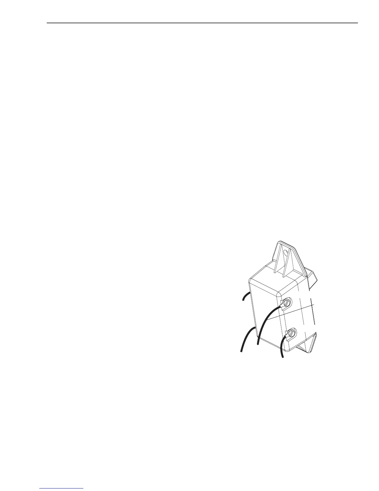
6. Faulty ON/OFF switch
a. Disconnect primary input power. Set
the On/Off switch to ON (UP) position.
Test for continuity between terminals
1 and 2, and between terminals 3 and
4. If there is no continuity, replace the
ON/OFF Switch.
A-03500
Input Power Cord
Line 2
To PC Board
Terminal E1
To PC Board
Terminal E2
Input Power Cord
Line 1
Terminal 1
Terminal 2
Terminal 3
Terminal 4
7. Faulty Bias Transformer
a. Refer to PC Board Wiring Layout in the
Appendix. Test for 380-410 vdc be-
tween TP-21 and TP-101 on PC Board.
If voltage is not correct, replace the PC
Board.