cutmaster 39
SERVICE 5-12 Manual 0-4976
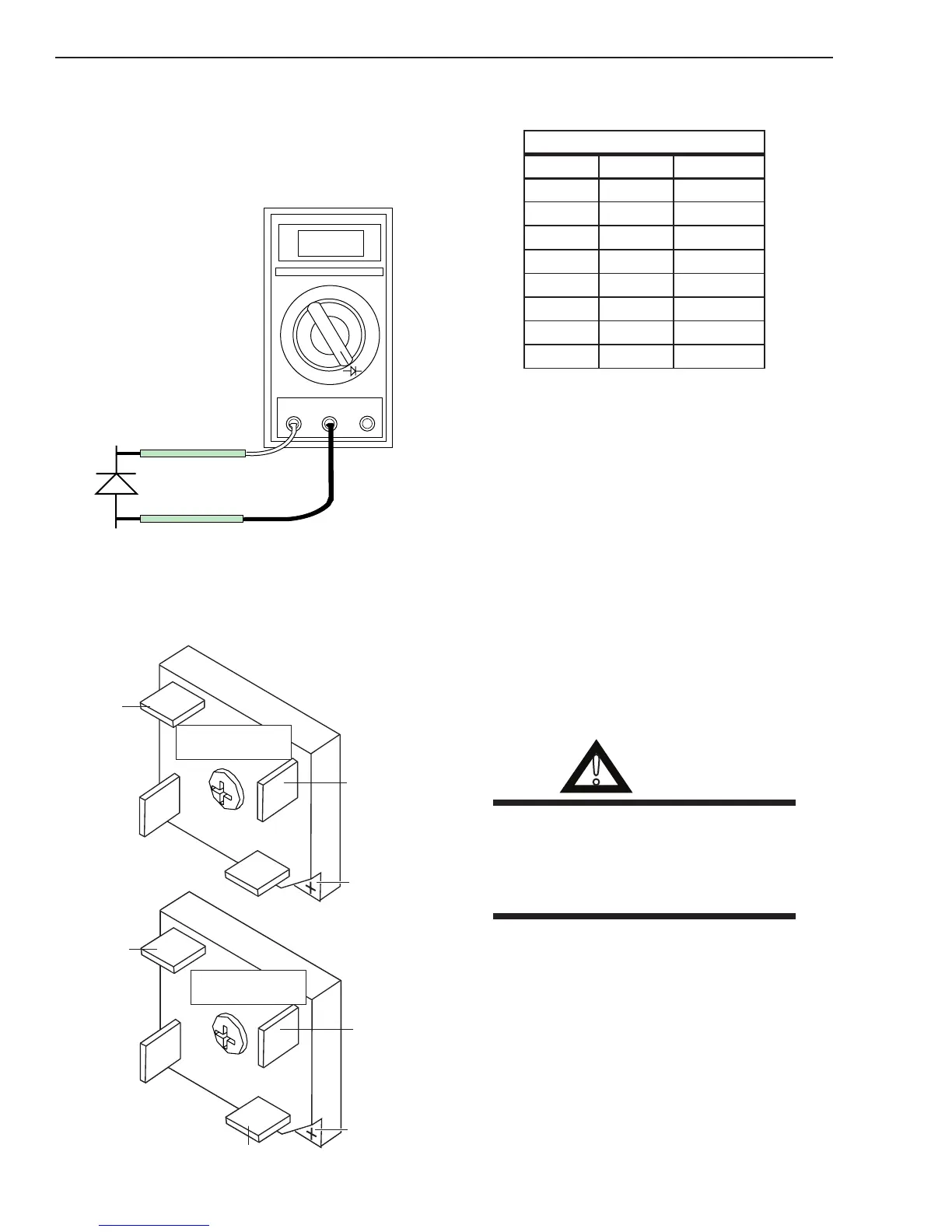
6. Reverse the meter leads across the diode
for reverse bias testing (refer to following
gure). A properly functioning diode will
block in the reverse bias direction and de-
pending on the meter function will indicate
an open or “OL”.
OL
VR
COM
A
Art # A-00306
Anode
Cathode
Reverse Bias
Diode Not Conducting
+
_
Testing Diode Reverse Bias
D. Diode Bridge Checks
Check for shorted Diode Bridges.
A-03508
E15B
E16B
E16A
E15A
E14A
E12A
+ Mark
E15B
E12B
E16B
E14B
Diode Bridge 1
Diode Bridge 2
+ Mark
Disconnect primary input power. With an ohm-
meter set on the diode range, make the following
checks on both diode bridges:
CutMaster 38 Diode Bridge Check
Meter (+) Meter (-) Indication
E16 E15 Diode Drop
E15 E16 Open
E16 E14 Diode Drop
E14 E16 Open
E14 E12 Diode Drop
E12 E14 Open
E15 E12 Diode Drop
E12 E15 Open
The meter should indicate a diode drop in one
direction and an open in the other direction for
each check.
5.08 Anti-Static Handling
Procedures
A. General
Caution: PC Boards can be irreparably damaged
by improper handling due to electrostatic dis-
charge (ESD).
Replacement PC Boards are shipped in a protec-
tive enclosure to prevent damage from electro-
static discharge (ESD) during shipping. Included
with each replacement board is a ground strap to
prevent static damage during installation.
WARNINGS
Read and understand these instructions and
the instructions on the grounding wrist strap
package before opening the equipment enclo-
sure or removing the replacement PC board
from its protective enclosure.
Disconnect primary power to the system before
disassembling the torch, torch leads, or power
supply enclosure.
Do not operate the equipment or test equipment
under power while wearing the grounding wrist
strap.
Observe torquing requirements where given.
Failure to torque properly will cause component
damage.