EasyManuals Logo

Thermal Dynamics CUTMASTER 39 User Manual

Thermal Dynamics CUTMASTER 39
82 pages
To Next Page IconTo Next Page
To Previous Page IconTo Previous Page
Page #68 background imageLoading...
Page #68 background image
cutmaster 39
PARTS LISTS 6-4 Manual 0-4976
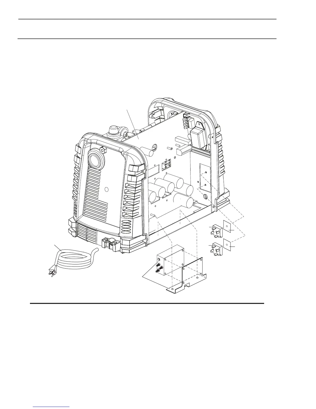
6.07 Left Side Replacement Parts
Item # Qty Description Ref Catalog #
1 1 PCB Assembly 9-0178
2 1 Diode Bridge BR1, BR2 7-3345
3 1 Thermal Pad 9-4466
4 1 Input Power Cable with plug, for non-CE units 9-8660
4 1 Input Power Cable for CE units 9-8671
4 1 Input Power Cable for (CE) Australian units 9-8663
Not Shown:
1 Power Cable Strain Relief, for all units 9-0111
A-08112
1
2
3
4
2
Input Filter & Bracket
(CE Units only)
3
NOTE
Illustration may vary slightly from unit.

Table of Contents

Questions and Answers:

Question and Answer IconNeed help?

Do you have a question about the Thermal Dynamics CUTMASTER 39 and is the answer not in the manual?

Thermal Dynamics CUTMASTER 39 Specifications

General IconGeneral
BrandThermal Dynamics
ModelCUTMASTER 39
CategoryWelding System
LanguageEnglish

Related product manuals