cutmaster 39
Manual 0-4976 4-3 OPERATION
4.02 Preparations For Operating
At the start of each operating session:
WARNING
Disconnect primary power at the source before assembling or disassembling power supply, torch parts,
or torch and leads assemblies.
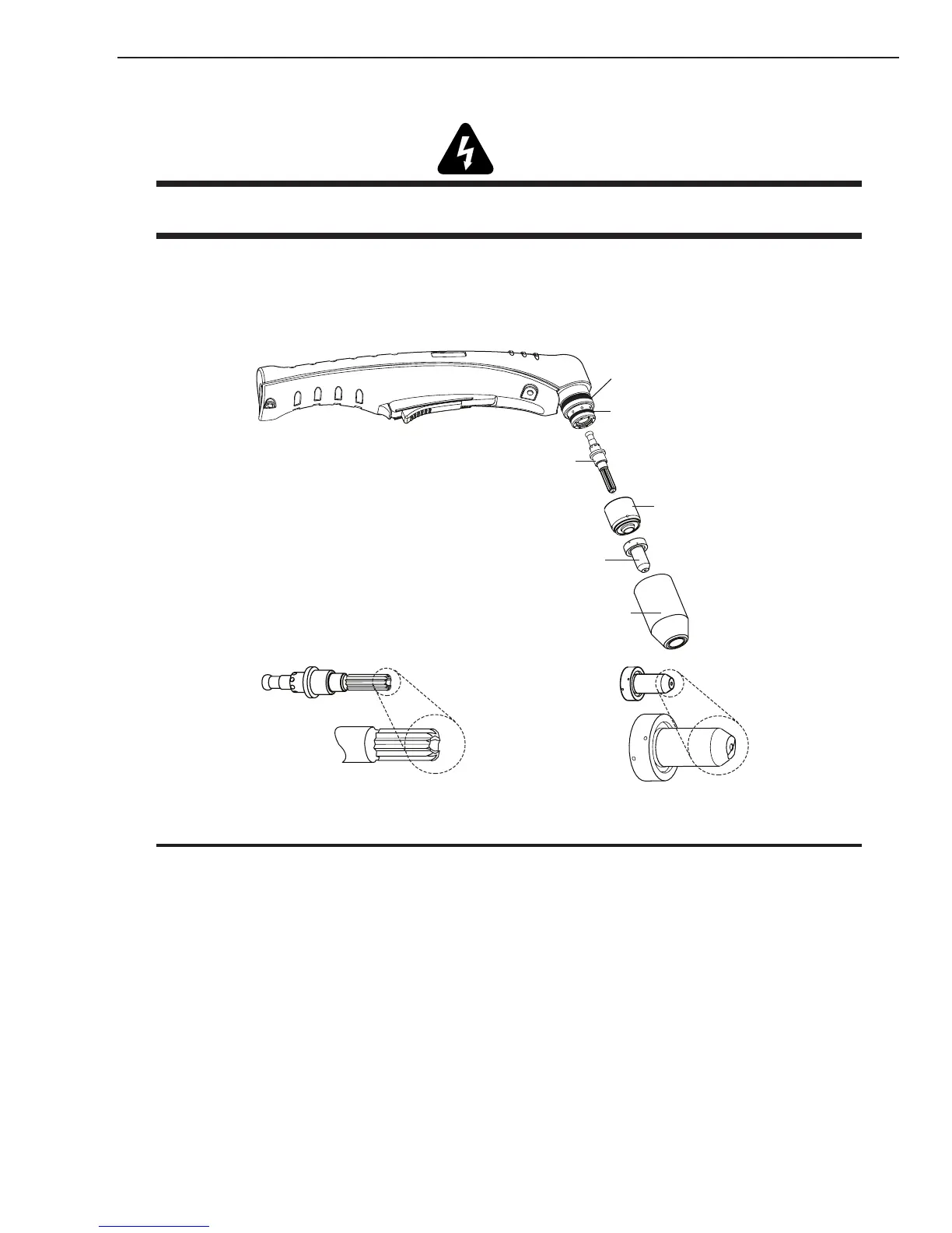
A. Torch Parts Selection
Check the torch for proper assembly and appropriate torch parts. The torch parts must correspond with the
type of operation, and with the amperage output of this Power Supply (30 amps maximum). Use only genuine
Thermal Dynamics parts with this torch.
Art # A-03409
Large O-Ring,
Cat. No. 8-3487
Small O-Ring,
Cat. No. 8-3486
Electrode, Cat. No. 9-8215
Start Cartridge,
Cat. No. 9-8213
30Amp Cutting Tip, Cat. No. 9-8206
Shield Cup, Cat. No. 9-8218
Worn Electrode
Worn Tip
NOTE
When operating the torch in a normal condition, a small amount of gas vents through the gap between the shield
cup and torch handle. Do not attempt to over tighten the shield cup as irreparable damage to internal components
may result.
B. Torch Connection
Check that the torch is properly connected.
C. Check Primary Input Power Source
1. Check the power source for proper input voltage. Make sure the input power source meets the
power requirements for the unit per Section 2, Specications.
2. Connect the input power cable (or close the main disconnect switch) to supply power to the sys-
tem.