cutmaster 39
SERVICE 5-16 Manual 0-4976
14. Reinstall the Power Supply cover. Con-
nect the gas input line to the inlet port.
Connect the Power Supply to primary input
power.
15. Test the Power Supply for proper opera-
tion.
C. Optional Single-Stage Filter Element
Replacement
NOTE
The Power Supply shuts down automatically
when the Filter Element becomes completely satu-
rated. The Filter Element can be removed from
its housing, dried, and reused. Allow 24 hours
for Element to dry.
1. Remove power from power supply.
2. Disconnect gas supply hose.
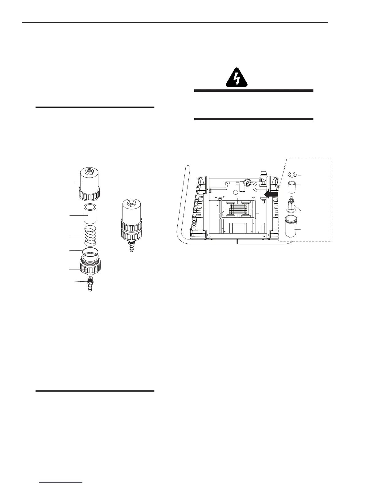
Art # A-02476
Filter
Element
(Cat. No. 9-7741)
Housing
Cover
Barbed
Fitting
Spring
Assembled Filter
O-ring
(Cat. No. 9-7743)
3. Turn the Cover counter-clockwise and re-
move it from the Filter Housing. The Filter
Element is located inside the Housing.
4. Remove the Filter Element from the Hous-
ing and set Element aside to dry.
5. Wipe inside of housing clean, then insert
the replacement Filter Element open side
rst, as shown.
6. Replace Housing on Cover.
7. Attach gas supply hose.
NOTE
If unit leaks between housing and cover, inspect
the O-Ring for cuts or other damage.
5.13 Right Side Internal Parts
Replacement
Refer to Section 6 for Right Side Internal
Parts List and overall detailed drawing.
WARNING
Disconnect input power at the source and
bleed down the system before attempting
these procedures.
A. Standard Filter Element Replacement
1. Remove the cover per Subsection 5.07-B.
2. Remove power from the power supply;
turn off the gas supply.
Art # A-07936
Replacement
Element
No. 9-0182
Ring
Spool
Bowl
3. Unscrew the bowl on the bottom of the
Regulator/Filter Assembly. The lter ele-
ment will be visible and still attached to the
main body of the Regulator/Filter Assem-
bly.
4. Grasp the lter element and unscrew it
from the Regulator/Filter body. The lter
element will come off with a spool and
some additional pieces.
5. Note the correct assembly of the lter/
spool then remove the lter from the
spool. Either clean or replace the lter ele-
ment.
6. The lter element and spool, with the
bafe ring in place (teeth facing down-
ward) can be screwed back into the Regu-
lator body by compressing the spring on
the spool. Tighten rmly by hand.
7. Reinstall the bowl. Connect the drain tube
to the bowl.
8. Reinstall Power Supply cover .
9. Turn on the air supply. Test the Power
Supply for proper operation.