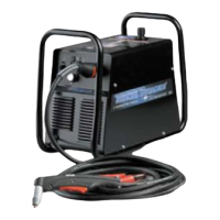
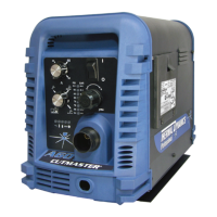
cutmaster 39
Manual 0-4976 5-17 SERVICE
B. Pressure Switch Replacement
1. Remove the cover per Subsection 5.04-A.
2. Label and disconnect the wires to the Pres-
sure Switch.
3. Turn the Pressure Switch to remove it from
the Regulator/Filter Assembly.
4. Apply thread sealant to the threads of the
replacement Pressure Switch.
NOTE
Do Not use Teflon tape as a thread sealer as small
particles of the tape may break off and block the
small gas passages in the torch.
5. Thread the replacement Pressure Switch
into place on the Regulator/Filter Assem-
bly. Tighten securely.
6. Connect the wires from the Pressure
Switch wire harness, with the wires posi-
tioned as marked previously.
7. Reinstall the Power Supply cover.
8. Reconnect the gas supply and primary
input power. Test the Power Supply for
proper operation.
 Loading...


