Chapter 3 | Replacing parts
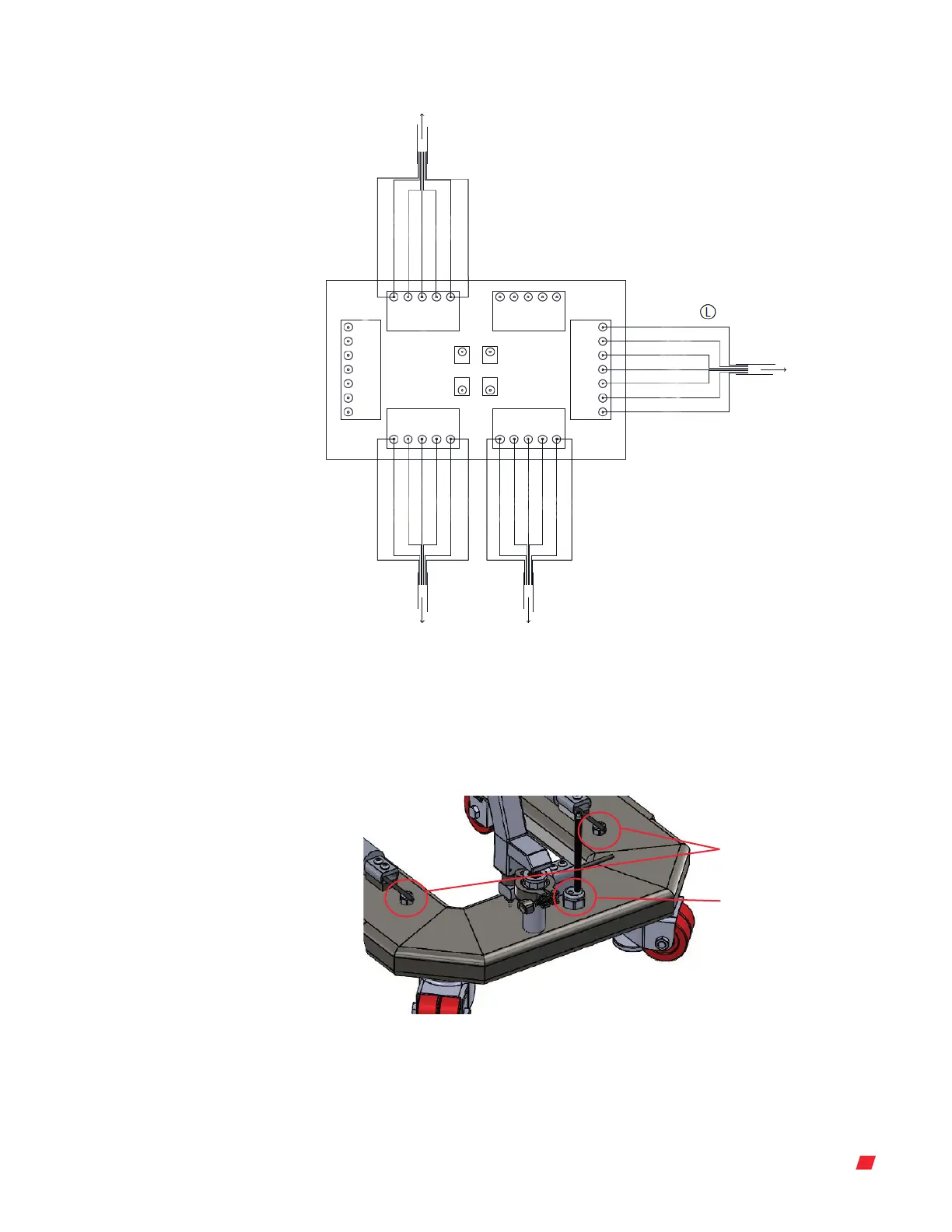
TO LOAD CELL 3TO LOAD CELL 1
TO LOAD CELL 2
YELLOW
GREEN
WHITE
YELLOW (LONG)
RED
BLACK
BLUE
+EXE
LC2
+SIG
SHLD
–SIG
–EXE
+EXE
+SIG
SHLD
–SIG
–EXE
+EXE
+SIG
SHLD
–SIG
–EXE
+EXE
+SIG
SHLD
–SIG
–EXE
LC4
LC1
LC3
LOAD CELL POTENIOMETER
+EXE
+SEN
SHLD
–SIG
+SIG
–SEN
–EXE
AUX
INPUT
+EXE
+SEN
SHLD
–SIG
+SIG
–SEN
–EXE
WHITE
YELLOW
GREEN
BLACK (SHIELD)
BLACK
RED
BLUE
TO ANALOG INDICATOR
Tie the grey and pink wires shield
Wiring colors shown are for the suggested Mettler
Toledo cable. If another cable is used, it is up to the
manufacturer to determine a wiring schematic. This
schematic must be kept on file and provided when
asked for. A standard cable should be decided on and
wired per a standard schematic.
Note:
Do not cut load cell cables to length.
Use original cable and length provided from vendor.
All cables must be the same length.
YELLOW
YELLOW
GREEN
GREEN
WHITE
WHITE
YELLOW (LONG)
YELLOW (LONG)
RED
RED
BLACK
BLACK
BLUE
BLUE
Mettler Toledo
Summing Block
Note:
Do not cut load cell cables to length.
Use original cable and length provided from vendor.
All cables must be the same length.
Figure 3.49. Wiring diagram showing connections from the load cell cables to the Mettler
Toledo Summing Block.
3. Feed the load cell wires into the liquid tight fitting and through to the summing block
(Figure 3.50). DO NOT CUT ANY LENGTH OFF OF THE LOAD CELL WIRES.
Figure 3.50. Feeding wire through the liquid tight.
Liquid tight(s)
Center liquid tight
Note: The center liquid tight fitting has two holes: one is for the center load cell, the
other is for the summing block cable.
Thermo Scientific 32DynaDrive S.U.B. Service Guide









 To Next Page