5-11
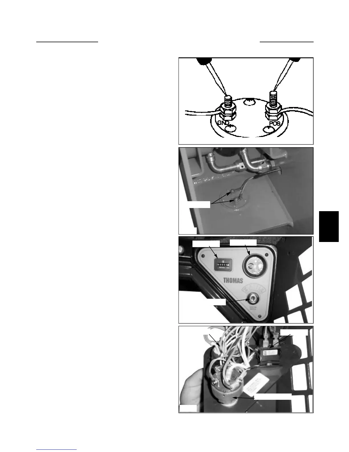
1 With the ignition switch off, connect an ohmmeter
between the positive and negative terminals of the fuel
sending unit. (fig. C306)
2 An ohmmeter reading of 50 to 500 is normal. A read-
ing higher or lower means a faulty sender and will need
replaced.
Testing the Fuel Sender
C306
C3582
Replacement
1 Remove any attachment, raise the boom arms and
engage the boom support pins. Shut off the engine and
engage the parking brake.
2 Remove the 2 wires connected to the fuel sending
unit. The fuel sender is located just below the lift cylin-
der, right hand side, on the fuel tank.
3 Remove the 5 screws retaining the sender to the fuel
tank.
4 Remove the sending unit and discard the gasket.
5 Install a new sending unit and gasket. Use gasket
sealant on both sides of the gasket.
6 Use thread sealant on the screws and torque the
screws to 20 inch / lbs. (fig. C3582)
7 Connect the sender wires taking care not to over
tighten the nuts and stripping the studs. Green wire is
ground.
Testing the Hour Meter
The hour meter records the number of engine operating
hours.
To check the hour meter, remove the 3 screws retaining
the right hand dash panel to the dash pod. (fig. C3580,
C3581)
Using a 12 volt test meter, connect the positive lead to the
positive terminal of the hour meter and the ground lead of
the tester to a good ground. Turn the ignition switch to
the “RUN” position.
A reading of 12 volts means the hour meter is operating
properly.
No voltage reading means there could be a problem in the
wire running from the “ACC” terminal on the ignition
switch to the positive side of the hour meter or a defec-
tive ignition switch.
C3581
Ignition switch
Fuel gauge
Hour meter
C3580
Ignition switch
Fuel gauge
Hour meter
INSTRUMENTATION 5.3
Fuel gauge