5-9
INSTRUMENTATION 5.3
Legend for fig. C3577
1 LH Turn Signal
2 Aux. Hydraulic Indicator
3 Hi-Flow Hydraulic Indicator
4 Headlight Indicator
5 RH Turn Signal
6 Hyd. Oil Temperature Indicator
7 Parking Brake Indicator
8 Seat Belt Indicator
9 Hyd. Charge Pressure Indicator
10 Strobe Light Indicator
11 Engine Oil Pressure
12 Engine Coolant Temperature
13 Alternator Indicator
14 Air Filter Restriction Indicator
15 Engine Preheat Indicator
16 Headlight Switch
17 Strobe Light Switch
18 Four Way Flasher Switch
19 Work light Switch
20 Aux. Hydraulics Switch
21 Hi-Flow Hydraulic Switch
22 Spare Switch Hole
23 Spare Switch Hole
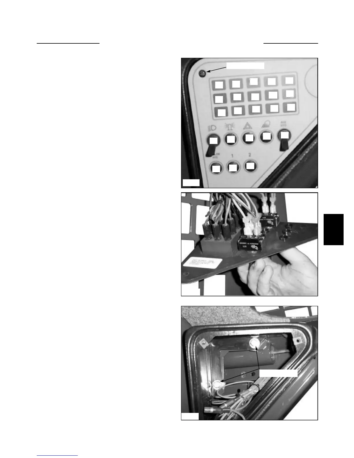
To replace a malfunctioning switch or indicator light:
1 Remove the 3 screws retaining the electrical panel to
the dash pod. (fig. C3577, C3578)
2 Disconnect the spade terminals on the rear of the
switch. (fig. C3578)
3 Remove the switch by loosening the hex nut on the
back, then unscrewing the knurled nut on the front of the
electrical panel.
4 Replace an indicator bulb by turning out the socket
and pull bulb out.
5 Replace the switch, indicator light and panel in the
reverse order.
C3578
C3577
C3579
17
16
15
14
13
12
11
10
9
87
6
5
43
2
1
Mounting bolts
If the dash pod is damaged, remove the 2 mounting bolts
and slip over the dash panel. (fig. C3579)
Disconnect all panel wiring if replacing the complete unit.
Replace the parts in reverse order. Follow the wiring
schematic to properly locate the switches and wiring in
position.
Switch & Bulb Replacement
18
19
20
21
22
23
Retaining Screw