CYLINDER HEAD 7.2
Valve Adjustment
The engine used in this application uses a solid lifter (tap-
pet) design that requires periodic maintenance of the
rocker arm to valve clearance. (Valve lash)
Valve clearance should be checked every 500 hours of
operation. Always check the valve clearance while the
engine is cold. Correct valve clearance is 0.18 ~
0.22mm (0.0071 ~ 0.0087in).
Procedure to Check / Adjust the Valve Clearance:
1 Park the loader on a level surface, lower the boom
arms, engage the parking brake and shut off the engine.
Remove the ignition key for safety.
2 Allow the engine to cool to room temperature.
3 Access the engine compartment by opening the rear
door and lifting the engine compartment cover.
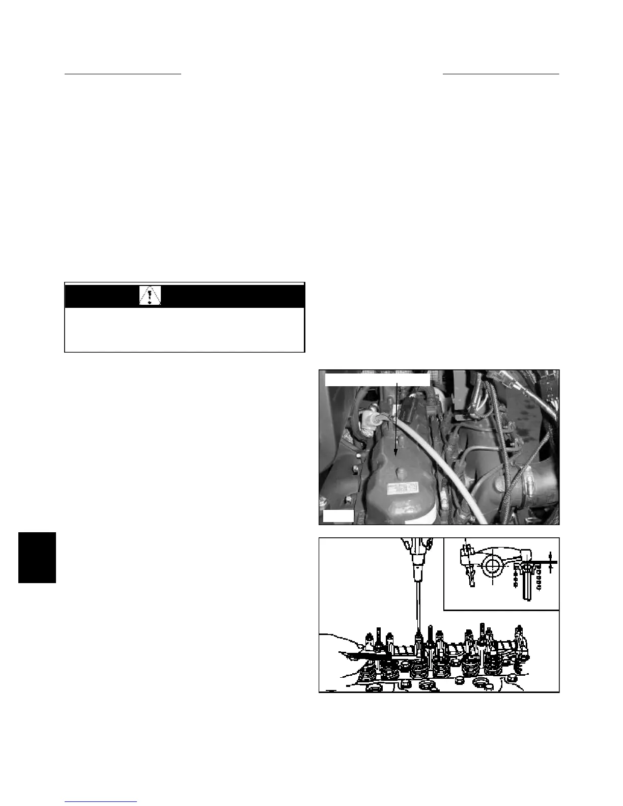
4 Remove the 4 nuts and washers retaining the valve
cover to the engine cylinder head and remove the cover.
(fig. C3613)
NOTE: The crankshaft pairs pistons # 1 and # 4, and pis-
tons # 2 and # 3 to rise and fall at the same time. The
camshaft valve timing though, has the cylinder pairs on
different cycles of operation.
Example: If both pistons on # 1 and # 4 were at top dead
center (TDC), one of the cylinders would be on the com-
pression stroke (both valves closed) the other cylinder
would be starting the intake stroke. (Intake valve starting
to open).
5 Turn the engine over until the intake valve is just
starting to open on number 1 (one) cylinder. (Cylinder
closest to radiator) This valve action means that cylinder
number 4 (next to flywheel) is on the compression stroke,
with both valves closed. This is the proper point to check
and / or adjust the intake and exhaust valves on cylinder
number 4.
6 Insert a feeler gauge between the rocker arm and the
intake or exhaust valve on cylinder number 4. (fig. C551)
If necessary, loosen the jam nut on top of the rocker arm
and turn the adjustment screw to acquire correct valve
clearance. Correct valve clearance is 0.18 ~ 0.22mm
(0.0071 ~ 0.0087in).
7-12
C3613
C551
Valve / rocker arm cover
7 Rotate the engine after checking / setting cylinder
number 4 valves, until cylinder number 4 intake valve
start to open. This position means that cylinder number 1
(one) is on the compression stroke and can have the
intake and exhaust valves checked and / or adjusted.
Correct valve clearance is 0.18 ~ 0.22mm (0.0071 ~
0.0087in).
8 Repeat the procedure for cylinder pairs 2 and 3. As
one of the cylinders intake valves are just starting to open
the opposite cylinder is on the compression stroke and
can have it’s valves adjusted.
Correct valve clearance is 0.18 ~ 0.22mm (0.0071 ~
0.0087in).
9 Rotate the engine 2 ~ 3 complete revolutions and
recheck the valve clearances by repeating the procedure
above.
10 Replace the valve cover. Tighten the mounting nuts
to 6.9 ~ 8.8 Nm (5.1 ~ 6.6 ft / lbs).
WARNING
Do not adjust the valve clearance while the engine is
hot. Clearances provided are for cold engine adjust-
ment only.