4-10
Angle Adjustment
The foot pedal angle can be verified and / or adjusted to
provide operator comfort and proper pedal travel clear-
ance.
Note: If the operator feels discomfort due to current pedal
angles, they may be adjusted to their preference. Be sure
to check for pedal travel clearance afterward. Always
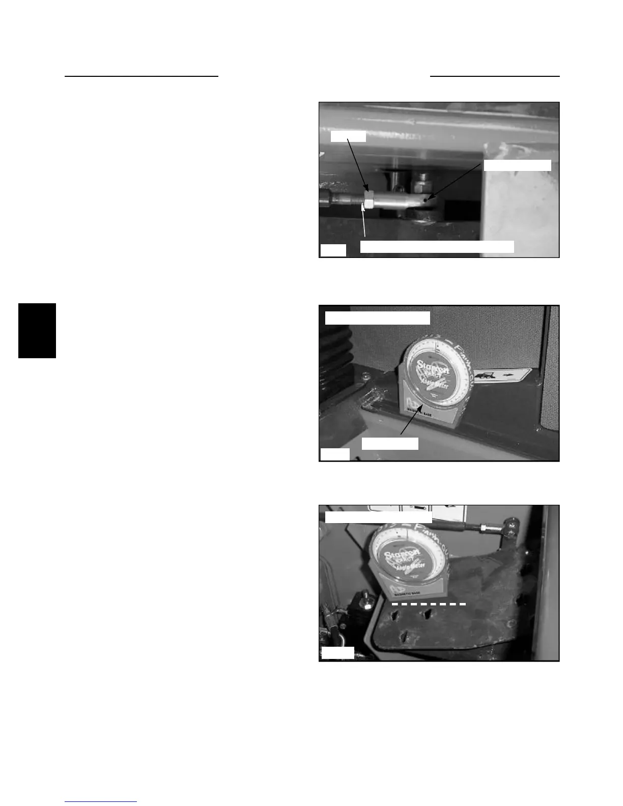
maintain a minimum of 3/8’’ (6mm) of thread into the
cable clevis and eyelet cable ends. (fig. C3563)
1 Make sure the cable ends are screwed onto the cable
threads a minimum of 3/8’’ (6mm). (fig. C3563)
2 Place an angle finder on the inner ROPS frame bot-
tom of the loader to find the base measurement. Note the
reading. (fig. C3564)
C3563
Cable Rod End
C3564
Checking the base angle
Angle finder
Jam nut
Checking the pedal angle
C3565
Maintain 3/8’’ (6mm) thread contact
4 Adjust the pedal angles by turning the rod ends on
the end of the linkage attached to the pedals. Adjust the
lift and tilt pedal angle to 20º.Be sure to allow for the
base angle measurement taken previously. Example: If the
base angle measured 3º, add or subtract that angle from
the angle measured on the pedal.
3 Place the angle finder on the heel of the pedal to be
checked or adjusted. (fig. C3565) Note the reading.
FOOT PEDALS 4.2