ENGINE MAINTENANCE 7.1
Universal Joint
The engine drive universal is located and accessed by
removing the operators seat, and removing the service
access cover. The universal joint should be serviced every
50 hours. Check the universal joint for wear and lubricate
with a standard grade of muti purpose grease.
To Service the U- Joint:
1 Remove any attachment, raise the boom arms,
engage the boom supports, engage the parking brake and
shut off the engine. Remove the ignition key.
2 Remove the seat assembly. Be sure to disconnect the
electrical plug on the seat switch, left hand side.
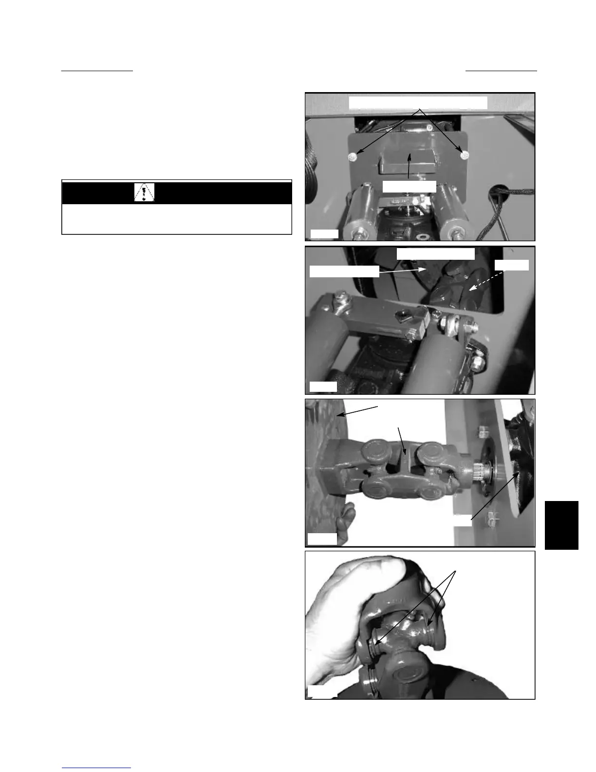
3 Remove the service access panel, located below the
battery compartment cover, by removing the 2 bolts and
lifting and pulling forward from the top. (fig. C3628)
4 Grasp the U- Joint assembly with your hands and
rotate the joint left and right, forward and back to check
U- Joint wear.
5 Check the condition of the splined yoke and spline
on the hydrostatic pump input shaft.
4 Rotate the U- Joint if necessary to locate the grease
fittings on the U- Joint crosses. Apply 2 ~ 3 pumps of
multi purpose grease to each U- Joint cross.
NOTE: Remove the U- Joint assembly from the loader to
replace worn U- Joints. (fig. C2226) The U- Joints are
retained by internal snap ring clips. Loosen the engine
mounting isolators to move the engine rearward enough
to allow the engine U-joint to come off the hydraulic tan-
dem pump splined shaft.
7-11
C3628
C2226
C3630
C3629
U- Joint assembly
Engine flywheel
Hydrostatic pump
U-Joint service access panel bolts
Lift and pull
Service panel open
Engine flywheel
U- Joint
U- Joint snap ring
WARNING
Never work under the boom arms without the boom
supports engaged