Rev: 2.2, 31-Jan-2022 © 2022 Thorlabs Page 16
DC4100 4 Computer Interface
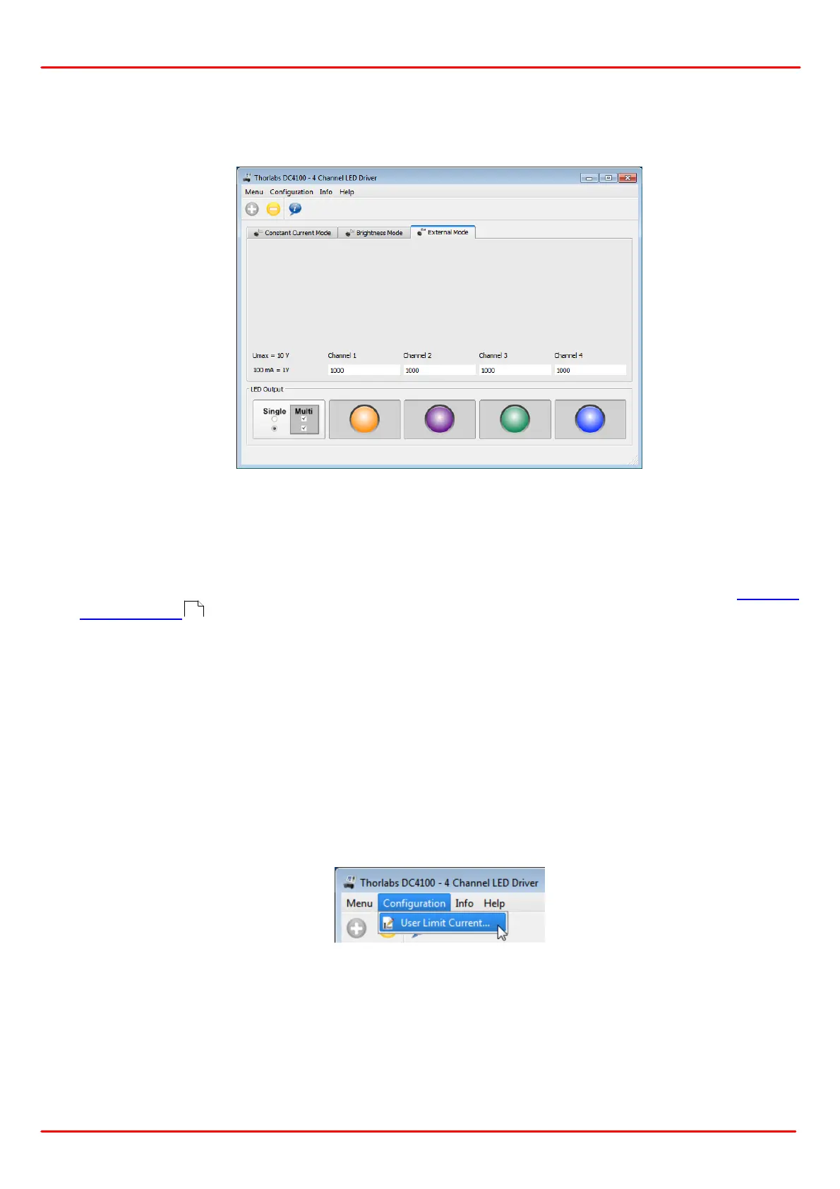
4.4.4 External Control Mode
Use the 'External Control Mode' to modulate/control the DC4100 by an signal from an external
signal generator. Click on the tab 'External Mode' to open the appropriate interface.
The LEDs can then be controlled only via the BNC connector at the rear panel of the DC4100.
The applied voltage corresponds to the LED current in that 1 V is equivalent to a LED current of
100 mA. A maximum voltage of 10 V can be applied, which will result in a current of 1 A. All
LED channels will be addressed by the control voltage, provided they are enabled by clicking
on the LED figure below the corresponding channel indicator, similar to the hardware External
Control Mode .
The button in the left lower corner is used to change between the output modes 'Single Selec-
tion' and 'Multi Selection'. Within the 'Single Selection Mode' only one LED can be enabled
while within the 'Multi Selection Mode' up to four LEDs can be used.
4.4.5 User Limit Current
For each LED, and individual current limit can be set. The supported Thorlabs LEDs feature an
EEPROM with the LED maximum current limit stored. This maximum current is imported by the
DC4100 and its software. The user current limit can be manually set below or equal to this
maximum current limit.
Select 'Configuration -> User Limit Current...' from the menu.
8