OPERATING MANUAL TW63 MOUNTING THE MACHINE
ThyssenKrupp Aufzugswerke GmbH
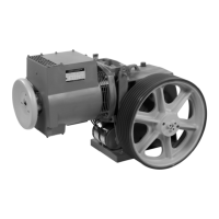
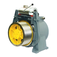
5. Mounting the machine
Depending on the scope of the order, the TW63 gear drive is delivered with
machine base frame and deflecting pulley. The base frame is installed and
set up depending on the customer on supports, beams, a concrete pedestal
or directly cast in concrete in the machine room floor.
For installation and mounting of the base frame supports, a drawing and
parts list are enclosed with the base frame.
Important: Use the enclosed mounting parts to mount the base frame
according to the drawing. Comply with the specified tightness and the
corresponding tightening torques. See details in chapter 9.1.
In order to comply with regulations for noise abatement and sound
transmission, isolation elements are to be inserted between the frame
supports and the ground.
The number of rubber elements is based on the total weight load. The
required individual load should be between 7 KN and 12 KN per element.
The location and arrangement of the rubber elements can be found in the
plan of installation.
Note: On arrangement of the supports, it is to be taken into account that the
overall centre of gravity lies within the rubber elements (also in the case of
elevator car suspension on the deflecting pulley side).
If the supporting surface of the machine base frame is cast as a cement floor,
the floor thickness should be ≤ 60 mm. Isolation elements with supports
(80 mm high) are to be inserted. Part of the base is also to be cast in the
floor.
You will find assembly instructions and data for the machine base frame in
chapter 3, Aligning the machine
The machine is to be set up according to the plan of installation (drawing).
The rope departure from the traction sheave is to be aligned plumb to the
elevator car mounting or the elevator car rope pulley and the counterweight
according to the drawing. With load applied to the ropes, the machine should
be aligned vertically on its installation surface. Irregularities are to be
balanced out by inserting shims under the floor support.
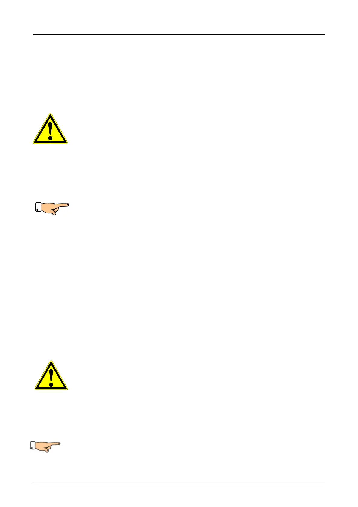
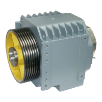
SA9 traction sheave in the shaft, machine with extended traction sheave
shaft and pedestal bearing.
Important: On setting up a gear drive with pedestal bearing, it must be
ensured without fail that
• the compensating supports are mounted and secured according to
instructions
• the traction sheave shaft is aligned horizontally
• the bearings of the machine and the outside bearing are exactly aligned
5.1 Note on connecting motors
Connecting the motor: on connecting the motor, the enclosed terminal
connecting plan in the motor terminal box and/or the terminal connecting plan
and corresponding building codes are to be complied with.