ii
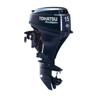
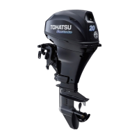
4st 9.9/15/20 2008
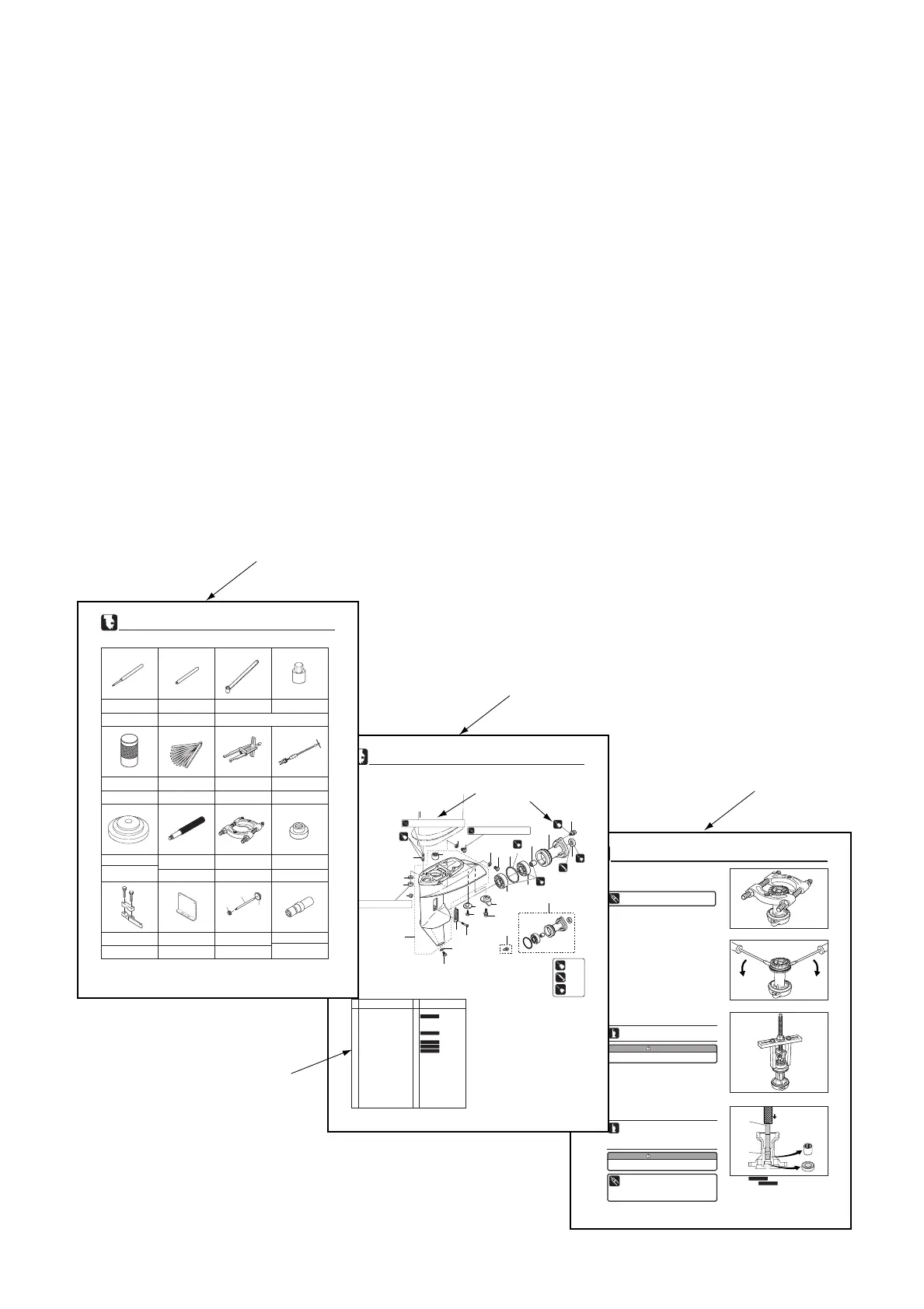
About this manual
This service manual is designed so that service persons are able to perform their work correctly.
Understand the following matters well for efficient repairs.
1 Each chapter begins with the introduction of special tools that are used for the work described in the
chapter so that the service persons are able to figure out the tools needed.
2 Parts that are serviced in each chapter and their details are presented by using a component composition
diagram.
3 Fastening torques are described in the component composition diagram and in the body text and are
critical points of the applicable repair.
4 Pictograms indicate that there is an important instruction for the relevant parts. It also shows the type of
lubricant and its application point(s).
5 The component composition diagrams describe the names of the parts, the quantity of the parts used,
size of fasteners and special notes.
6 Specific works are described in detail by using illustrations and adding advice on the work.
6-12
Lower Unit
4st 9.9/15/20 2008
Do not reuse removed bearing.
3. Use commercially available universal puller plate to remove
ball bearing.
4
3
2
3
4. Use a press to remove oil seal 2 and needle bearing 3 at
the same time.
Before removing, check bearing for play or
deflection. Replace if necessary.
Before removing, check bearing for play or
deflection. Replace if necessary. Direct
attachment with side without O-ring to needle
bearing.
Do not reuse removed bearing.
Needle Bearing Attachment 3 :
P/N. 3BA-99710-0
Driver Rod 4 :
P/N. 3AC-99702-0
2 Oil seal
3 Needle bearing
Do not reuse.
Do not reuse.
10)
Disassembly of Propeller Shaft Housing
1. Tighten universal puller plate to make gap between reverse
gear (C gear) and propeller shaft housing.
2. Remove reverse gear (C gear) ass'y by putting two bladed
screw drivers into the gap to force the gap to open.
Universal Puller Plate :
P/N. 3AC-99750-0
6-4
Lower Unit
4st 9.9/15/20 2008
18
20
19
17
1
1-1
5
3
5
4
8
7
6
10
9
2
2
11
12
13
14
21
22
16
15
5
3
14N·m (10 lb·ft) [1.4 kgf·m]
TB
1342342134 2
1342
G
R
E
A
SE
OBMOBMOBM
OBM
OIL
GEARGEARGEAR
GEAR
O
IL
GEARGEARGEAR
GEAR
O
IL
GEARGEARGEAR
GEAR
TB
1342342134 2
1342
19 N·m (14 lb·ft) [1.9 kgf·m]
24 N·m (17 lb·ft) [2.4 kgf·m]
2.Parts Layout
Gear Case
1 Gear Case 1
1-1 Needle Bearing 1
2 Ball Bearing, 6205HS 2
3 Oil Plug 2
4 Water Plug 1
5 Gasket, 8.1-15-1 3
6 Propeller Shaft Housing 1
7 Needle Bearing, 17-24-20 1
8 O-Ring, 2.4-59.6 1
9 Oil Seal, 17-30-9 1
10 Bolt 2
11 Trim Tab 1
12 Bolt 1
13 Sub Water Strainer 1
14 Screw 1
15 Water Strainer 2
16 Screw 1
17 Nylon Nut, 4P-0.7 1
18 Stud Bolt 4
19 Nut 4
20 Washer, 8.1-16-1.5 4
21 Propeller Shaft Housing Ass'y 1
22 Sub Water Pipe Plug 1 Option
Ref.
No.
Description
Remarks
Q'ty
O
IL
GEARGEAR
GEAR
OBM
1342
P/L Fig. 14
Do not reuse.
Do not reuse.
Do not reuse.
Do not reuse.
Do not reuse.
6-2
Lower Unit
4st 9.9/15/20 2008
1.Special Tools
Removing spring pin
Spring Pin Tool A
P/N. 345-72227-0
Used with driver rod and needle
bearing attachment
Positioning propeller shaft housing
needle bearing
Driver Rod
P/N. 3AC-99702-0
Center Plate
P/N. 3AC-99701-0
Used with center plate and
needle bearing attachment
Used with driver rod Installing oil
seal in the propeller shaft housing
Oil Seal Attachment 2
P/N. 3AG-99820-0
Installing forward (A) gear
bearing
Removing/installing Pinion (B) Gear Nut
Bevel Gear Bearing Installation Tool
P/N. 346-72719-0
Bevel Gear B Nut Wrench
P/N. 346-72231-0
Bevel Gear B Nut Socket
P/N. 346-72232-0
Slide Hammer Kit
P/N. 3AC-99080-0
Removing forward (A) gear
bearing outer race
Universal Puller Plate
P/N. 3AC-99750-0
Removing forward (A) gear
bearing outer race
Bevel Gear Bearing Puller Ass'y
P/N. 3A3-72755-0
Installing spring pin
Spring Pin Tool B
P/N. 345-72228-0
Installing forward gear (A)
bearing outer race
Bearing Outer Press Kit
P/N. 3B7-72739-1
Removing reverse
gear/bearing
3BJ-72733-0
3B7-72731-0
3BJ-72732-0
Needle Bearing Attachment
P/N. 3BA-99710-0
Used with driver rod and center plate
Installing propeller shaft housing
needle bearing
Measuring gaps
Thickness Gauge
P/N. 353-72251-0
Measuring backlash
Backlash Measuring Tool Clamp
P/N. 3B7-72720-0
ø110 x ø71 ø29.5 x ø16.5
Used to attach dial gauge
whwn measuring backlash
Dial Gauge Plate
P/N. 3B7-72729-0
E_MFS20C_ch00_081218.qxd 09.1.20 5:09 PM ページ 2
 Loading...