6-22
Lower Unit
4st 4/5/6 2011
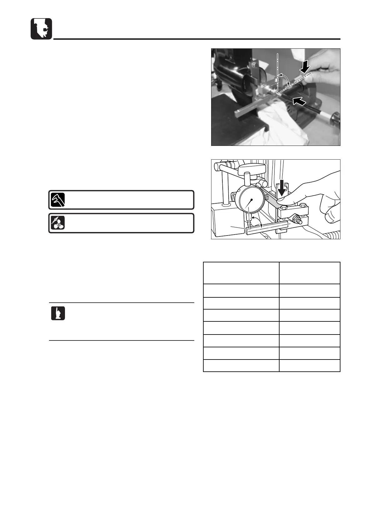
4. Perform shim adjustment at pinion (B) gear side as
necessary based on the gauge value obtained. The table
shows relation between dial gauge readings and shim
adjustments.
3. Secure clamp halves A and B to shaft B using bolts. Move
clamp A while pushing arm in direction a, and read dial
gauge at notch groove b position.
Gauge Reading Shim Adjustment
mm mm
0.00 - 0.15 -0.10
0.16 - 0.49 0
0.50 - 0.52 +0.25
0.53 - 0.59 +0.30
0.60 - 0.65 +0.35
0.66 - 0.71 +0.40
0.72 - 0.77 +0.45
2. First, pull up drive shaft by using hand.
Fix shaft B with bladed screw driver, and tighten nut while
pushing the shaft. At this time, be careful not to overtighten
the nut, or shaft B is locked.
Tighten nut fully by using fingers, and then, additionally
tighten approximately 90 degrees by using spanner wrench.
During the work, fix shaft B by using bladed screw driver.
1.Values in this table indicate dial gauge readings
that are obtained when using special tool.
2.Change gear engagement position and
measure backlash again for check.
Sizes of Adjusting Shims :
For Pinion (B) Gear Side : 0.1, 0.15mm
Proper Backlash Obtained from Gauge Reading :
0.16 - 0.49mm (0.0063 - 0.0193 in)
MFS4-5-6Ech06110422.qxd 11.4.22 5:50 PM ページ22
 Loading...