6-26
Lower Unit
4st 4/5/6 2011
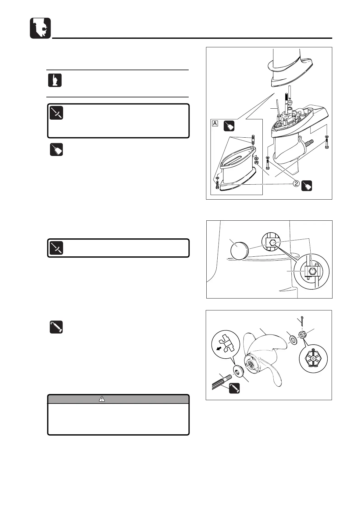
5. Apply OBM grease to propeller shaft 7.
6. Attach thrust holder 8, propeller 9, washer 0 and propeller
nut q to propeller shaft. Put a piece of wooden block
between anti-cavitation plate and propeller to prevent
rotation of propeller, and tighten propeller nut to specified
torque.
)
2
1
TB
13423421342
1342
TB
13423421342
1342
3
2. Attach lower unit ass'y to drive shaft housing, and tighten
lower unit installation bolts 2 (nut 3 ) to specified torque.
3. Install cam rod 1 to joint 4 and tighten bolt 5 to specified
torque.
Joint Bolt 5 :
6 N · m (4 lb · ft) [0.6 kgf · m]
4. Attach grommet 6 to drive shaft housing.
Connect water pipe securely. Move flywheel a
little to align the drive shaft spline to crank shaft
spline.
OBM
Lower Unit Installation Bolts (M8)2 :
6 N · m (4 lb · ft) [0.6 kgf · m]
Lower Unit Installation Bolt, Nut (M8)3 :
13 N · m (9 lb · ft) [1.3 kgf · m]
å UL-Transom Model
Before removing or installing propeller, be
sure to disconnect spark plug cap and
remove stop switch lock plate.
1342
MFS4-5-6Ech06110422.qxd 11.4.22 5:50 PM ページ26
 Loading...