◇22
Chapter 4 Basic operation
4.1 Interface structure overview
This chapter describes the operation of withstanding voltage and insulation resistance.
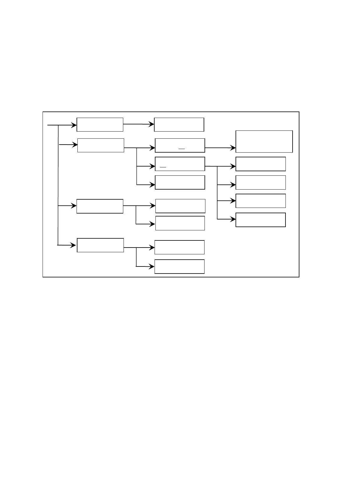
The following figure is the interface structure:
Operation Steps
Introduction to the interface:
The first line in the interface structure shows the initial states corresponding to the function keys on
the panel (see sections 4.3, 4.4 for more details.) The TEST interface cannot modify parameters.
The second line in the interface shows the parameter structures of the initial interface. For example:
STEP 01/01 in the SETUP interface means that it is the step 1 of the programme and the total steps is
1; AC: means the AC withstanding voltage test interface; AC parameter means that other parameters
are AC withstanding voltage test parameters.
The third line in the interface is the function toggle interface. When some function lablels are
selected in the second interface, the corresponding functions can be changed and their relative
parameters will also vary. For instance, changing AC to DC, the tester will change from the AC
withstanding voltage test mode to the DC withstanding voltage test mode, and the current AC
parameter will be changed into DC parameter.
NOTE:
1. Turn on the power while pressing F4 key, the instrument will restore factory defaults.
2. Clear extent: SETUP (test condition) and SYSTEM (system setup).
3. When the software is updated or display error caused by recalling archive of low
fileversion is encountered, using this method to restore the normal work of the instrument.