6-3
A3524 Rev 1.1
Installing Topcon Hiper-AG RTK Fixed Base Station
Topcon Hiper-AG unit
Topcon UHF Radio
The high-gain Collinear (shing pole) Antenna (Figure 6-1 on page 6-1)
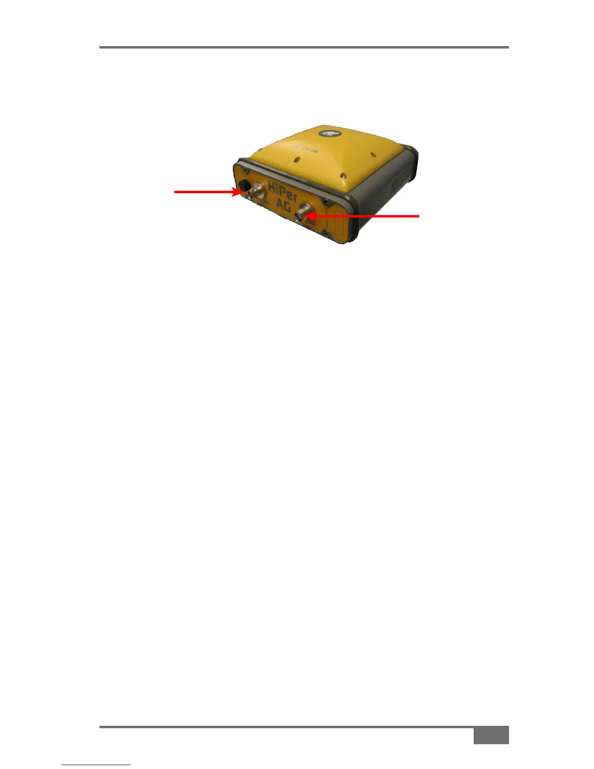
is connected to the BNC Connector of the Hiper-AG unit (Figure 6-3 on
page 6-2), via a thick black RG213 cable.
The RG213 cable has identical N-type connectors at each end.
There is a short adaptor cable supplied with a male N-type at one end
and a BNC connector at the other.
Screw the male N-Type connector of the adaptor cable to the 1.
female N-type connector of the RG213 cable
Connect the BNC connector on the other end of the short adaptor 2.
cable to the top of the Hiper-AG’s bayonet tting (Figure 6-3 on
page 6-2)
See “UHF Collinear Antenna Cable-RG213” on page 6-11 to 3.
complete the connection.
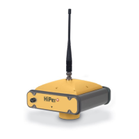
Figure 6-3. Hiper-AG unit
BNC
(Bayonet)
Connector
GPS Fitting