EasyManuals Logo

Topcon A3524 User Manual

Topcon A3524
48 pages
To Next Page IconTo Next Page
To Previous Page IconTo Previous Page
Page #30 background imageLoading...
Page #30 background image
6-8
www.topconpa.com
Topcon GPS Manual
Enhancing GPS and Radio Performance
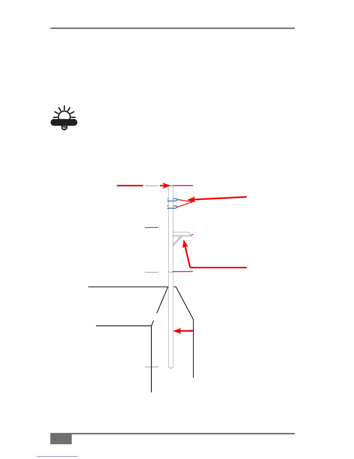
Please note: The Antenna Mast is to be supplied by the end user, and is
not included in the Hiper-AG Base Station kit. The following diagram
and description is the ideal GPS and Radio Antenna support bracket.
Manufacture and erection of this mast to an
outbuilding/tower will enhance GPS and radio
performance.
TIP
TIP
Figure 6-7. Lightning Arrestor Support Bracket
1 Meter
1 Meter
2 Meters
1.5” Galv. Tubing
Stainless steel
hose/exhaust
clamps
Weld plate
(700mmx150mm)
with support brace
Apex of shed roof/
tower
Secure to
shed/ tower
Manufacture
pole from 1.5”
(38mm) galv.
tubing
Secure radio
antenna to
the bracket
using either
stainless steel
exhaust or
hose clamps
Weld a flat
base, 27”
(700mm) x
4” (100mm),
with a strut
support to
the pole. This
is the GPS
antenna plate.

Questions and Answers:

Question and Answer IconNeed help?

Do you have a question about the Topcon A3524 and is the answer not in the manual?

Topcon A3524 Specifications

General IconGeneral
BrandTopcon
ModelA3524
CategoryGPS
LanguageEnglish

Related product manuals