D4008 – EN EZ 2810 Operators Manual 35
SECTION 6 – INSTALLATION
6.1.0 Indicator Mounting
For most applications the equipment manufacturer provides the necessary mounting system and
hardware and mounts the Indicator for the End User.
Digi-Star provides a number of mounting options that allow the end user to customize the location
and placement of the Indicator. The following section provides a list of the optional mounts.
In all cases the Digi-Star Indicator must be securely mounted to the equipment. Loose, or
unsupported, Indicators can be damaged.
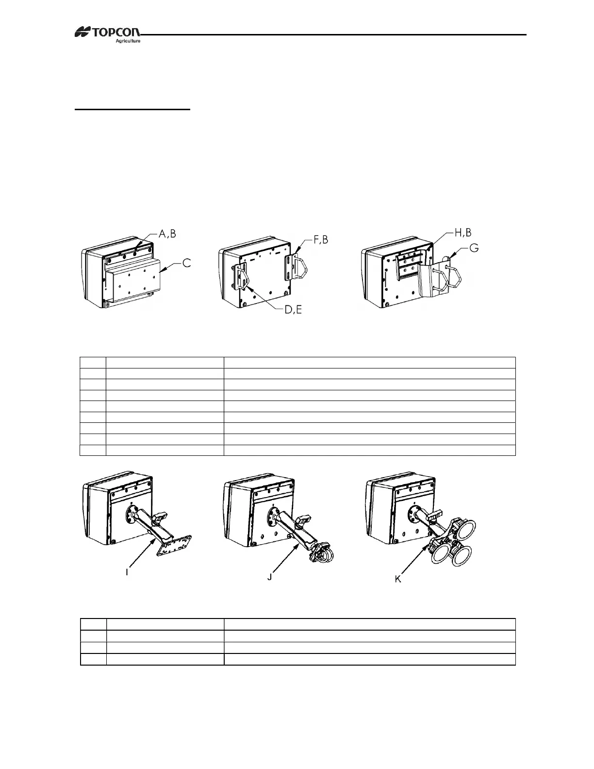
STD UNIVERSAL WING MOUNT WEDGE MOUNT
MOUNT TALL
KEY
PART NUMBER DESCRIPTION
A 404353 BRACKET-EZ3 PLASTIC RAIL *
B 403780 SCR-#10 X 5/8 FHSTS BLACK ZP
C 840459 SUPPORT-HAT BRACKET
D 405069 U-BOLT 1/4-20 X 3.25 ZP
E 405084 NUT-1/4-20 TOP LOCKING FLANGE
F 403770 BRACKET- WING MOUNT *
G 405124 PACK-WEDGE MOUNT BRACKET WITH U-BOLTS & FLANGE NUTS
H 405244 EZ3 WEDGE MOUNT
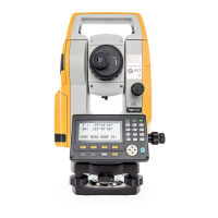
RAM MOUNT
KEY
PART NUMBER DESCRIPTION
I 404799 KIT-1.5” RAM MOUNT WITH BOLT-ON BASE WITH HARDWARE
J 407544 KIT-1.5” RAM MOUNT WITH DUAL U-BOLTS (FITS 0.5”-1.5” ROUND)
K 407434 KIT-1.5” RAM MOUNT WITH TRIPLE SUCTION CUP BASE